


13
Before Use
Connections (continued)
To enjoy DVD video with a higher image quality
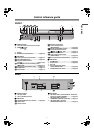
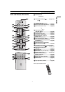
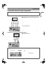
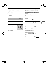
Connection to a TV using the COMPONENT VIDEO OUT terminal (progressive out)
ª COMPONENT VIDEO OUT terminal (progressive out)
These terminals can be used for either interlace or progressive output and
provide a purer picture than the S-VIDEO OUT terminal.
Connection using these terminals outputs the color difference signals (P
B
/
P
R
) and luminance signal (Y) separately in order to achieve high fidelity in
reproducing colors.
≥The description of the component video input terminals depends on the
television or monitor (e.g. Y/P
B
/P
R
, Y/B-Y/R-Y, Y/C
B
/C
R
). Connect to
terminals of the same color.
≥When making this connection, ensure you connect the audio cables (not
supplied) to the corresponding audio input terminals on the television.
≥After making this connection, change the black level for a better picture
(Black Level Control lpage 49).
To enjoy progressive video
1) Connect to the component video input terminals on a 480P compatible
television. (Video will not be displayed correctly if connected to an
incompatible television.)
2) In SET UP menus, set “Progressive Out (Component)” to “Enable”
(lpage 49).
3)
Change “Video output mode” to “480P” in the on-screen menu
(l
page 46
).
≥
All televisions manufactured by Panasonic and that have 480P input connectors
are compatible. Consult the manufacturer if you have another brand of television.
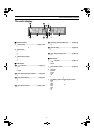
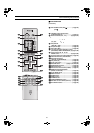
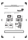
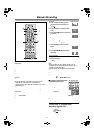
Connection to a TV using the S-VIDEO OUT terminal
ª S-VIDEO OUT terminal
The S-VIDEO OUT terminal achieves a more vivid picture than the VIDEO
OUT terminal by separating the chrominance (C) and luminance (Y) signals.
(Actual results depend on the television.)
≥When making this connection, ensure you connect the audio cables to the
corresponding audio input terminals on the television.
≥Connect to a different terminal group (e.g., “VIDEO 2”) than that you used
for the connection through this unit’s OUT1 (VCR/DVD) terminal.
Picture from this unit’s VCR will not appear when you use the same group
input terminal connections because the S-video terminal input takes
precedence.
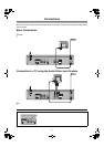
The following connections are for the DVD section only.
Carry out the Basic Connections described on the left page to view video from the VCR section.
≥You may need to change the video-input mode on the TV to view video from the VCR and DVD sections. Read your television’s
operating instructions for details.
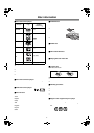
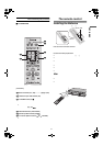
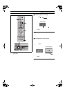
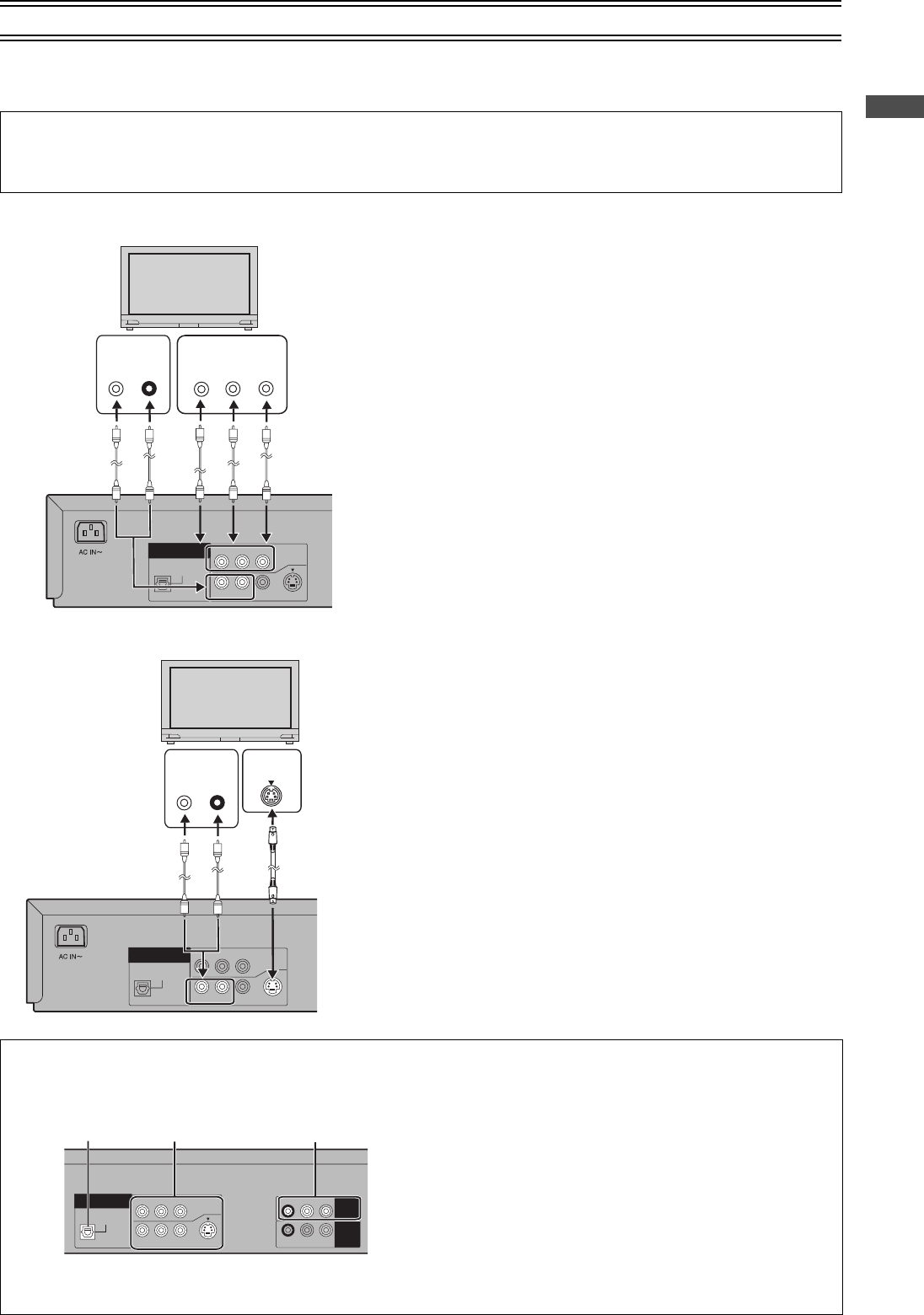
About the output terminal common to VCR and DVD and the one exclusively for DVD
This unit has an output terminal common to VCR and DVD and one exclusively for DVD.
≥For the OUT1 (VCR/DVD) terminal, VCR and DVD outputs can
be switched or it can be assigned for VCR output only.
≥The OUT2 terminal can only output the DVD signal.
Note:
≥Even if “AUTO” is selected in “OUT1 [VCR/DVD]” of the VCR
MENU
“
OPTION” (lpage 30), the desired output may not be
selected depending on the operation.
In this case, press [VCR/DVD OUTPUT] on the remote controller
to switch manually.
≥When Video is switched to DVD or vice versa, the audio volume
may suddenly increase or decrease.
This is because when the audio output of this unit is connected
to the TV, etc., the audio output of the DVD is generally lower.
When you increase the volume level to play back DVD audio,
reduce it when playback is finished.
OPTICAL
DIGITAL
AUDIO OUT
(PCM/BITSTREAM)
R-AUDIO-L
VIDEO
S-VIDEO
COMPONENT
VIDEO OUT
(480P/480I)
Y
P
B PR
OUT2
(DVD ONLY)
COMPONENT
VIDEO IN
Y
P
B
P
R
AUDIO IN
L
R
(Not supplied) (Not supplied)
OPTICAL
DIGITAL
AUDIO OUT
(PCM/BITSTREAM)
R-AUDIO-L
VIDEO
S-VIDEO
COMPONENT
VIDEO OUT
(480P/480I)
Y
P
B PR
OUT2
(DVD ONLY)
AUDIO IN
L
R
IN
S VIDEO
(Not supplied)(Not supplied)
R-AUDIO-L
VIDEO
OPTICAL
DIGITAL
AUDIO OUT
(PCM/BITSTREAM)
R-AUDIO-L
VIDEO
S-VIDEO
COMPONENT
VIDEO OUT
(480P/480I)
Y
P
B
P
R
OUT2
(DVD ONLY)
R-AUDIO-L
VIDEO
IN
(AV1)
OUT1
(VCR/DVD)
DVD-only terminal
OPTICAL DIGITAL
AUDIO OUT terminal OUT2 terminal
Output common to
VCR and DVD
OUT1 (VCR/DVD)