


Connecting up
02
14
En
+6Chapter 2
Connecting up
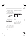
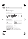
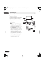
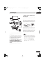
Rear panel connections
1 AV1(RGB)-TV AV connector
Audio/video output SCART-type AV
connector for connecting to a TV or other
equipment with a SCART connector. The
video output is switchable between video, S-
video and RGB. See page
AV1 Out
on
page 119 for how to set this up.
2 OUTPUT
Stereo analog audio, video and S-video
outputs for connection to a TV or AV
amplifier/receiver.
3 AV2(INPUT 1/DECODER) AV
connector
Audio/video input/output SCART-type AV
connector for connecting to a VCR, or other
equipment with a SCART connector. The
input accepts video, S-video and RGB. See
AV2/L1 In
on page 119 for how to set this up.
4 ANTENNA IN (RF IN)/OUT
Connect your TV antenna to the
ANTENNA
IN (RF IN)
jack. The signal is passed through
to the
ANTENNA OUT
jack for connection to
your TV.
5 AC IN – Power inlet
6 DIGITAL AUDIO OUT
Coaxial digital audio jack for connecting to
an AV amplifier/receiver, Dolby Digital/DTS/
MPEG decoder or other equipment with a
digital input.
7 CONTROL IN
Use to control this recorder from the remote
sensor of another Pioneer component with a
CONTROL OUT
terminal and bearing the
Pioneer
mark. Connect the
CONTROL
OUT
of the other component to the
CONTROL IN
of this recorder using a mini-
plug cord.
8 G-LINK™
Use to connect the supplied G-LINK™ cable
to enable GUIDE Plus+® to control an
external satellite receiver, etc.
9 COMPONENT VIDEO OUT
A high-quality video output for connecting to
a TV or monitor with a component video
input.
AC IN
DIGITAL
OUT
CONTROL
G-LINK
COAXIAL
IN
S-VIDEO
VIDEO
AUDIO
L
R
COMPONENT
VIDEO OUT
Y
P
B
P
R
ANTENNA
IN
OUT
OUTPUT
AV 1 (RGB) – TV AV 2 (INPUT 1/DECODER)
1 2
5 6 7 8 9
3 4
DVR540H_WV_EN.book 14 ページ 2006年2月16日 木曜日 午後4時34分