


15
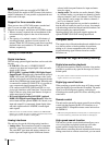
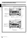
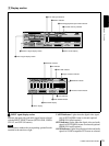
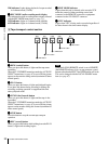
Location and Function of Parts
Chapter 1 Overview
a
aa
a POWER switch
Press the “” side to power on the unit. This causes the
audio level meters and the display section to light. To
power off the unit, press the “” side of the switch.
b
bb
b Audio level meters
These two meters indicate the recording audio levels
during recording or EE mode* and the playback audio
levels during playback. When the audio level indicated on
a meter exceeds 0 dB, the OVER indicator for the meter
lights.
The short bars to the right of level indication bars indicate
that those levels are reference audio recording levels.
The settings made with the METER CH-1/2 3/4 button and
MONITOR SELECT button select the audio channels for
level indications on these meters as follows.
When CH-1/2 mode is selected with the METER CH-1/
2 3/4 button:
Every time the MONITOR SELECT button is pressed,
the audio channel selection for level indications on the
two meters cycles through the following options.
• CH-1 (channel 1) only
Only the CH-1 indicator lights.
• CH-2 (channel 2) only
Only the CH-2 indicator lights.
• CH-1 and CH-2 (channels 1 and 2)
Both the CH-1 and CH-2 indicators light.
When CH-3/4 mode is selected with the METER CH-1/
2 3/4 button:
Every time the MONITOR SELECT button is pressed,
the audio channel selection for level indications on the
two meters cycles through the following options.
• CH-3 (channel 3) only
Only the CH-3 indicator lights.
• CH-4 (channel 4) only
Only the CH-4 indicator lights.
• CH-3 and CH-4 (channels 3 and 4)
Both the CH-3 and CH-4 indicators light.
* E-E mode: Abbreviation of “Electric-to-Electric mode.” In this mode,
video and audio signals input to the VCR are output after passing through
internal electric circuits, but not through magnetic conversion circuits such
as heads and tapes. This can be used to check input signals and for
adjusting input signal levels.
c
cc
c PHONES connector (stereo phone jack) and
control knob
Connect stereo headphones to the connector for audio
monitoring during recording or playback. The control
knob controls the volume of the headphones. It also
controls the level of the audio signal output from the
MONITOR connector on the rear panel.
The settings made with the METER CH-1/2 3/4 button and
MONITOR SELECT button select the audio channels for
audio output via this connector. The same channel
selection as for the audio level meters applies to this
connector.
d
dd
d SC (subcarrier phase) control
Turn this control to accurately adjust the subcarrier phase
of the composite video output signal of the unit with
respect to the reference video signal. Use a cross-point
(Phillips) screwdriver to turn it.
e
ee
e SYNC (synchronization phase) control
Turn this control to accurately adjust the synchronization
phase of the output video signal of the unit with respect to
the reference video signal. Use a cross-point (Phillips)
screwdriver to turn it.
f
ff
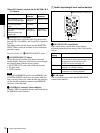
f Cassette compartment
Accepts DVCAM, DV and DVCPRO (25 Mbps)
videocassettes.
For details of usable cassettes, see page 29.
g
gg
g LOCAL/REMOTE switch
Selects whether the unit is operated from its front panel or
from external equipment.
REMOTE: The unit is operated from external equipment
connected to the REMOTE connector or i.DV IN/
OUT connector on the rear panel.
LOCAL: The unit is operated from its front panel or from
a SIRCS-compatible remote control unit connected to
the CONTROL S connector on the front panel.
h
hh
h EJECT button
When you press this button, the cassette is automatically
ejected after a few seconds.
i
ii
i MONITOR SELECT button
Use this button and the METER CH-1/2 3/4 button to
select the audio channels:
• for level indications on the audio level meters
• for audio output via the PHONES connector on the front
panel
• for audio output via the MONITOR connector on the
rear panel
Depending on the setting made with the METER CH-1/2
3/4 button, the channels for output to the above meters and
connectors are selected as follows.
When CH-1/2 mode is selected with the METER CH-1/
2 3/4 button:
Audio level meters PHONES
connector
MONITOR
connector
CH-1 (channel 1) only.
Only the left meter lights.
Channel 1 only
(monaural)
Channel 1 only
CH-2 (channel 2) only.
Only the right meter
lights.
Channel 2 only
(monaural)
Channel 2 only
CH-1 and CH-2 (channels
1 and 2).
Both the left and right
meters light.
Channels 1
and 2 (stereo)
Channels 1
and 2 (mixed)