


20
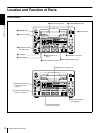
Location and Function of Parts
Chapter 1 Overview
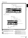
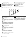
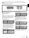
VIDEO indicators: The indicator (COMPOSITE, S
VIDEO, Y
−R,B, SDI, or SG) corresponding to the
selected input video signal format lights.
AUDIO indicators: Comprise the CH-1 1/2 indicator and
CH-2 3/4 indicator, under each of which there are four
more indicators (ANALOG, AES/EBU, SDI, and SG).
They indicate the selected input audio signal formats.
b
bb
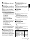
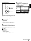
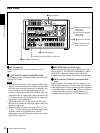
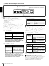
b OUTPUT signal display section
Indicates the output video and audio signal format selected
with the INTERFACE SELECT menu items (see page 75).
Note
The indicators without the corresponding optional boards
installed in the unit do not light.
SDI indicator: Lights when the digital video and audio
signals in SDI format are selected (optional DSBK-
1501 board required).
The SDI video and audio signals are output to the SDI/
SDTI (QSDI) OUT1 and OUT2 connectors.
SDTI indicator: Lights when the digital video and audio
signals in SDTI (QSDI) format are selected (optional
DSBK-1501 board required).
The video and audio signals in SDTI (QSDI) format
are output to the SDI/SDTI (QSDI) OUT1 and OUT2
connectors.
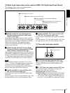
VIDEO indicators: The indicator (COMPOSITE, S
VIDEO, or Y
−R,B) corresponding to the selected
output analog video signal format lights.
This selection determines the signals output from the
Y/CPST, R
−Y/C/CPST, and B−Y/CPST (SUPER)
connectors as follows.
• When COMPOSITE is selected:
• When S VIDEO is selected:
• When Y
–
R,B is selected:
Indicators Meanings
COMPOSITE Composite video signal (optional
DSBK-1504/1504P board required)
S VIDEO S-video (separated Y and C) signals
(optional DSBK-1504/1504P board
required)
Y−R,B Y, R−Y and B−Y component video
signals (optional DSBK-1504/1504P
board required)
SDI SDI video signal (optional DSBK-1501
board required)
SG Video test signal (factory default
setting)
Indicators Functions
CH-1 1/2
(ANALOG, AES/
EBU, SDI, SG)
The indicator corresponding to the
signal format selected for audio input
to channel 1 (when in 2-channel
mode) or to channels 1 and 2 (when
in 4-channel mode) lights.
ANALOG: Analog audio signal
(optional DSBK-1504/1504P
board required)
AES/EBU: Digital audio signal in
AES/EBU format (optional
DSBK-1501 board required)
SDI: SDI audio signal (optional
DSBK-1501 board required)
SG: Audio test signal (factory default
setting)
CH-2 3/4
(ANALOG, AES/
EBU, SDI, SG)
The indicator corresponding to the
signal format selected for audio input
to channel 2 (when in 2-channel
mode) or to channels 3 and 4 (when
in 4-channel mode) lights.
ANALOG: Analog audio signal
(optional DSBK-1504/1504P
board required)
AES/EBU: Digital audio signal in
AES/EBU format (optional
DSBK-1501 board required)
SDI: SDI audio signal (optional
DSBK-1501 board required)
SG: Audio test signal (factory default
setting)
Indicators Meanings
COMPOSITE Composite video signal
S VIDEO S-video (separated Y and C) signals
Y−R,B Y, R−Y and B−Y component video
signals
Connectors Output signals
Y/CPST Composite signal
R−Y/C/CPST Composite signal
B−Y/CPST (SUPER) Composite signal
Connectors Output signals
Y/CPST Y signal
R−Y/C/CPST C signal
(3.58 MHz for DSR-1500A/
4.43 MHz for DSR-1500AP)
B−Y/CPST (SUPER) Composite signal
Connectors Output signals
Y/CPST Y signal
R−Y/C/CPST R−Y signal
B−Y/CPST (SUPER) B−Y signal