


27
Location and Function of Parts
Chapter 1 Overview
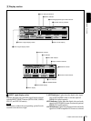
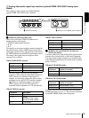
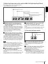
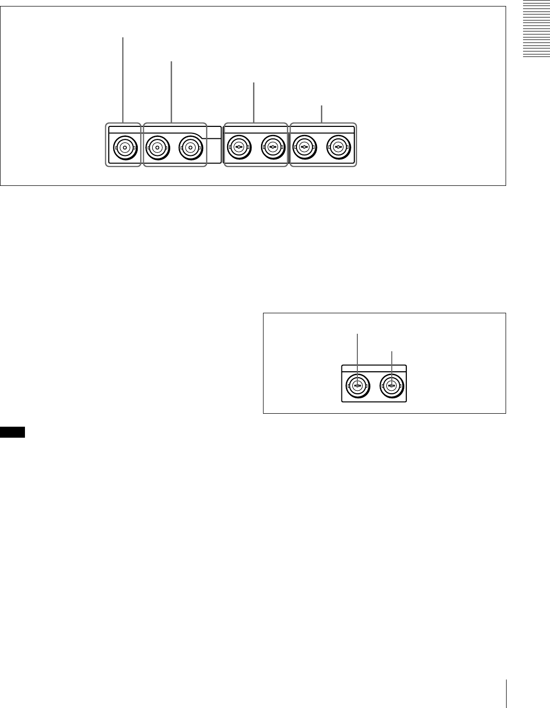
C Digital signal input/output section (optional DSBK-1501 Digital Input/Output Board)
The connectors in this section are available when the
optional DSBK-1501 board is installed.
a
aa
a SDI/SDTI (QSDI) IN (Serial Digital Interface/
Serial Data Transport Interface (QSDI) input)
connector (BNC type)
This connector inputs digital video and audio signals in
SDTI (QSDI) or SDI format. To select the required input
signal formats, use the SDTI/i.LINK button or VIDEO
button on the front panel. The current input signal
selections are indicated in the INPUT signal display
section on the front panel.
b
bb
b SDI/SDTI (QSDI) OUT1/OUT2 (Serial Digital
Interface/Serial Data Transport Interface (QSDI)
output 1/output 2) connectors (BNC type)
These connectors output digital video and audio signals in
SDTI (QSDI) or SDI format. To select these output signal
formats, use the DIGITAL OUTPUT menu item (see page
75). The current output signal selections are indicated in
the OUTPUT signal display section on the front panel.
Note
When searching at speeds in the range +
1
/
2
to +
1
/
30
or
−
1
/
2
to −
1
/
30
times normal speed, the audio signal output
from these connectors in SDTI (QSDI) format and
monitored on external equipment may sound differently
from the audio signal played back on this unit.
c
cc
c AUDIO (AES/EBU) IN 1/2 and AUDIO (AES/
EBU) IN 3/4 connectors (BNC type)
Input digital audio signals in AES/EBU format to these
connectors.
The left connector (1/2) is for audio channels 1 and 2, and
the right connector (3/4) is for audio channels 3 and 4.
d
dd
d AUDIO (AES/EBU) OUT 1/2 and AUDIO (AES/
EBU) OUT 3/4 connectors (BNC type)
These connectors output digital audio signals in AES/EBU
format.
The left connector (1/2) is for audio channels 1 and 2, and
the right connector (3/4) is for audio channels 3 and 4.
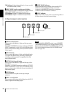
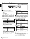
D Time code input/output section
a
aa
a TC IN (time code input) connector (BNC type)
Input externally generated SMPTE time code (for DSR-
1500A) or EBU time code (for DSR-1500AP) to this
connector.
b
bb
b TC OUT (time code output) connector (BNC type)
This connector outputs a time code according to the
operating state of the unit, as follows:
During playback: the playback time code
During recording: the time code generated by the internal
time code generator or the time code input to the TC
IN connector. When the EE OUT PHASE menu item
(see page 71) is set to MUTE, no time code is output.
IN OUT1 OUT2 IN
1/2 3/4 1/2 3/4
OUTAUDIO I/O (AES/EBU)
SDI/SDTI
(QSDI)
a SDI/SDTI (QSDI) IN connector
b SDI/SDTI (QSDI) OUT1/OUT2 connectors
c AUDIO (AES/EBU) IN 1/2 and AUDIO (AES/EBU)
IN 3/4 connectors
d AUDIO (AES/EBU) OUT 1/2 and AUDIO
(AES/EBU) OUT 3/4 connectors
INTC OUT
b TC OUT connector
a TC IN connector