


17
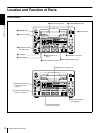
Location and Function of Parts
Chapter 1 Overview
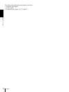
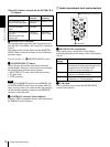
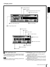
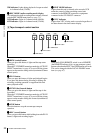
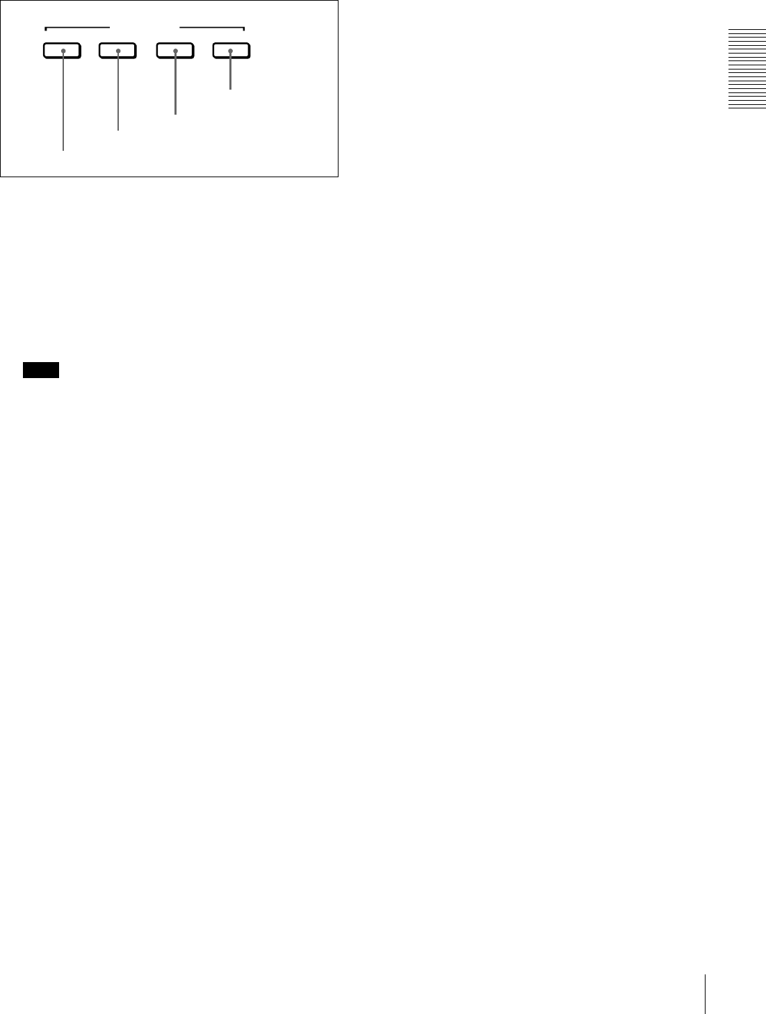
B Video/audio input setting section
a
aa
a SDTI/i.LINK (SDTI (QSDI) interface/i.LINK
selection) button
Each press of this button cycles through the following
input signal selection options.
• Digital video signal in SDTI (QSDI) format input to the
SDI/SDTI (QSDI) IN connector (optional DSBK-1501
board required)
When this is selected, use the CH1 1/2 button and CH2
3/4 button to select the required input audio signals.
Note
In this case, the phases of the selected audio signals
will be about two frames ahead of the phase of the
digital video signal in SDTI (QSDI) format.
• Digital video and audio signals in SDTI (QSDI) format
input to the SDI/SDTI (QSDI) IN connector (optional
DSBK-1501 board required)
• Digital video and audio signals in i.LINK-compatible
DV format input to the i.DV IN/OUT connector
The selection made with this button is indicated in the
INPUT signal display section (see page 20).
b
bb
b VIDEO button
Each press of this button cycles through the following
input video signal selection options.
•
Composite video signal input to the VIDEO IN
connector (optional DSBK-1504/1504P board required)
• S-video (separated Y and C) signals input to the VIDEO
IN connectors (optional DSBK-1504/1504P board
required)
• Y, R
−Y and B−Y component video signals input to the
VIDEO IN connectors (optional DSBK-1504/1504P
board required)
• SDI video signal input to the SDI/SDTI (QSDI) IN
connector (optional DSBK-1501 board required)
• Video test signal (selected with the INT VIDEO SG
menu item (see page 72)) generated by the internal
signal generator
The selection made with this button is indicated by the
VIDEO indicators in the INPUT signal display section (see
page 19).
c
cc
c CH1 1/2 (audio channel 1 or 1/2) button
Each press of this button cycles through the following
input audio signal selection options for audio channel 1
(when in 2-channel mode) or for audio channels 1 and 2
(when in 4-channel mode).
• Analog audio signal input to the AUDIO IN 1/3
connector (optional DSBK-1504/1504P board required)
• Digital audio signal in AES/EBU format input to the
AUDIO (AES/EBU) IN 1/2 connector (optional DSBK-
1501 board required)
• SDI audio signal input to the SDI/SDTI (QSDI) IN
connector (optional DSBK-1501 board required)
• Audio test signal (selected with the INT AUDIO SG
menu item (see page 74) generated by the internal signal
generator
The selection made with this button is indicated by the
AUDIO CH-1 1/2 indicators in the INPUT signal display
section (see page 19).
When analog audio is selected (optional DSBK-1504/
1504P board required), the signal input to the AUDIO IN
1/3 connector is recorded either on channel 1 (when in 2-
channel mode) or on channels 1 and 3 (when in 4-channel
mode). That is, in 4-channel mode, the same analog audio
signal is recorded on channels 1 and 3. Using the REC/PB
LEVEL control knobs with the VAR switch set to REC, it
is possible to adjust the audio levels on the two channels
separately.
You can switch the audio recording mode with the REC
MODE menu item (see page 73). The selection is indicated
by the REC MODE display on the front panel.
d
dd
d CH2 3/4 (audio channel 2 or 3/4) button
Each press of this button cycles through the following
input audio signal selection options for audio channel 2
(when in 2-channel mode) or for audio channels 3 and 4
(when in 4-channel mode).
• Analog audio signal input to the AUDIO IN 2/4
connector (optional DSBK-1504/1504P board required)
• Digital audio signal in AES/EBU format input to the
AUDIO (AES/EBU) IN 3/4 connector (optional DSBK-
1501 board required)
• SDI audio signal input to the SDI/SDTI (QSDI) IN
connector (optional DSBK-1501 board required)
• Audio test signal (selected with the INT AUDIO SG
menu item (see page 74) generated by the internal signal
generator
The selection made with this button is indicated by the
AUDIO CH-2 3/4 indicators in the INPUT signal display
section (see page 19).
When analog audio is selected (optional DSBK-1504/
1504P board required), the signal input to the AUDIO IN
2/4 connector is recorded either on channel 2 (when in 2-
channel mode) or on channels 2 and 4 (when in 4-channel
mode). That is, in 4-channel mode, the same analog audio
signal is recorded on channels 2 and 4. Using the REC/PB
LEVEL control knobs with the VAR switch set to REC, it
INPUT SELECT
SDTI/i.LINK VIDEO
CH1 1/2 CH2 3/4
d CH2 3/4 button
c CH1 1/2 button
b VIDEO button
a SDTI/i.LINK button