


77
Menu Contents
Chapter 4 Menu Settings
EE OUT PHASE settings for time code
output
Use the following as reference information when setting
the EE OUT PHASE menu item (see page 71)
.
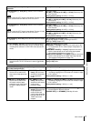
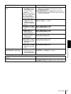
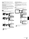
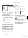
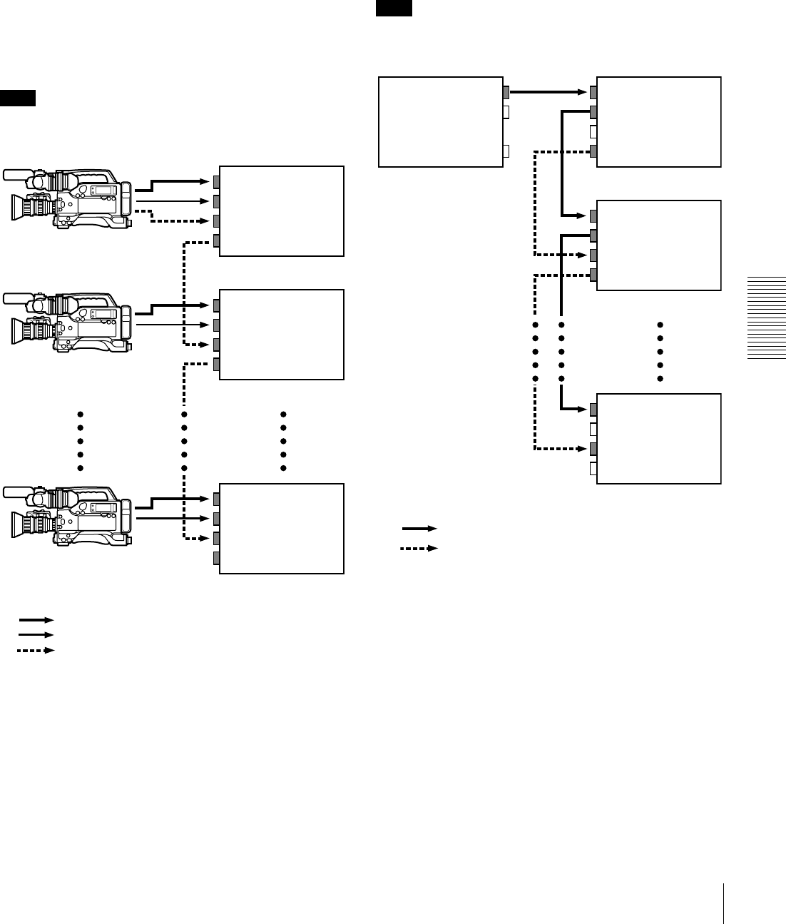
THROUGH mode
In this mode, the LTC signal is output with the phase
synchronized with the input time code signal. This mode is
appropriate when recording signals from multiple devices
on a number of VCRs.
When the camcorder is in genlock mode, the time code
precision is ±0 frames. When the camcorder is not in
genlock mode, it is ±1 frame.
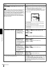
Note
The optional boards (see page 11) corresponding to the
input signal formats to be used are required.
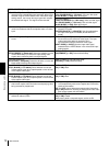
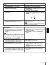
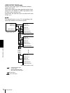
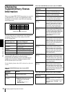
VIDEO INPUT PHASE mode
The time code output signal is synchronized with the input
video signal.
This mode is appropriate when the output from a single
device is recorded on a number of VCRs. The connections
are loop-through connections.
In this mode, the same time code is recorded on all of the
VCRs 1 to n.
Note
The optional boards (see page 11) corresponding to the
input signal formats to be used are required.
VIDEO IN
AUDIO IN
TIME CODE IN
TIME CODE OUT
VIDEO IN
AUDIO IN
TIME CODE IN
TIME CODE OUT
VIDEO IN
AUDIO IN
TIME CODE IN
TIME CODE OUT
Composite video or S-video signal
Audio signal
Time code signal
Camcorder 1
Camcorder 2
Camcorder n
DSR-1500A/1500AP (1st unit)
DSR-1500A/1500AP (2nd unit)
DSR-1500A/1500AP (nth unit)
VIDEO INVIDEO OUT
VIDEO LOOP THRU
TIME CODE IN
TIME CODE OUT
VIDEO IN
VIDEO LOOP THRU
TIME CODE IN
TIME CODE OUT
VIDEO IN
VIDEO LOOP THRU
TIME CODE IN
TIME CODE OUT
Composite video or SDI (video and audio) signal
Time code signal
DSR-1500A/1500AP (1st unit)
DSR-1500A/1500AP (2nd unit)
DSR-1500A/1500AP (nth unit)
Output device
(VCR, camera, etc.)