


24
Location and Function of Parts
Chapter 1 Overview
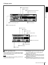
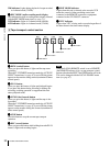
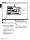
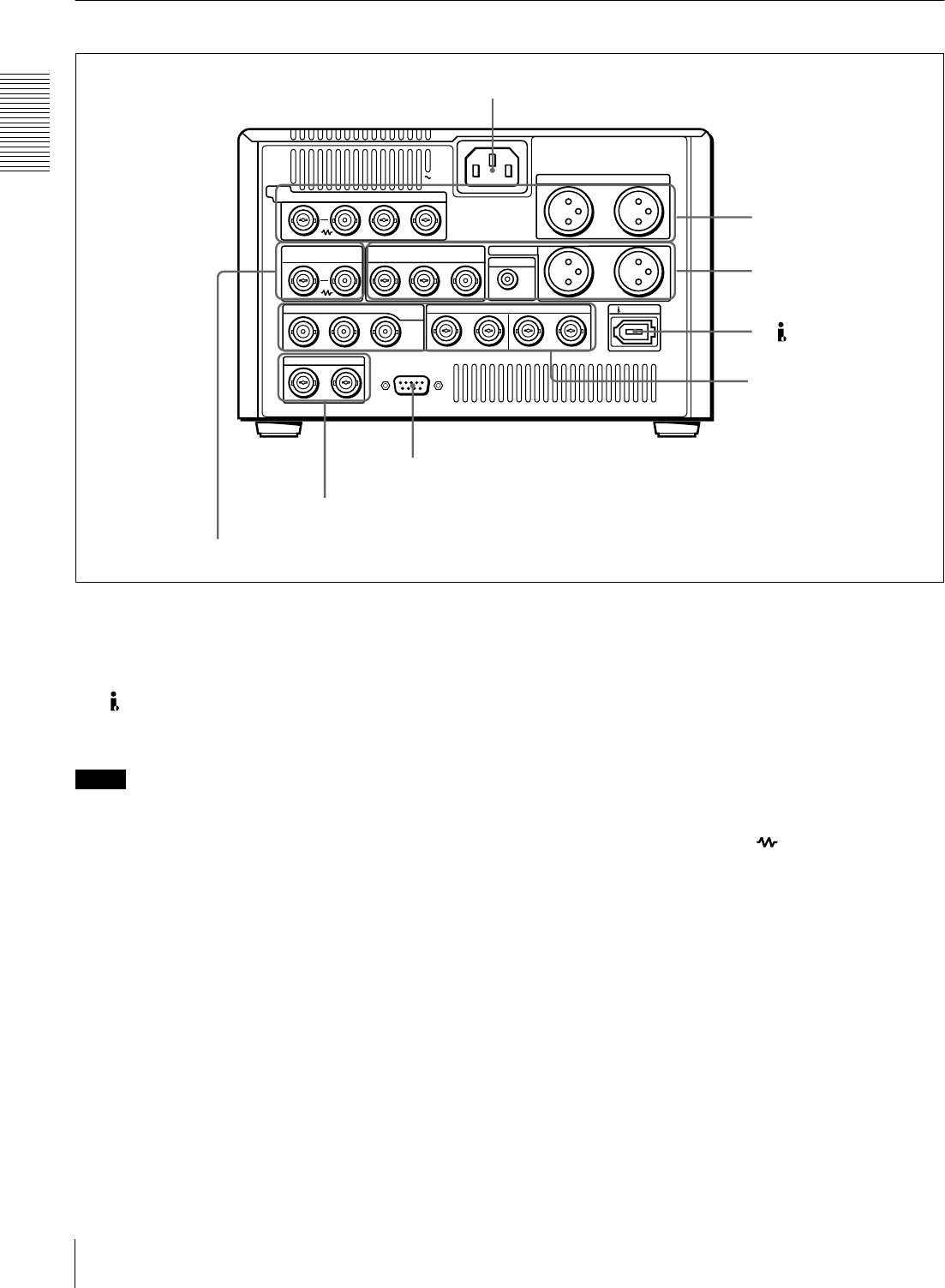
Rear Panel
a
aa
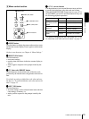
a AC IN connector
Use the supplied power cord to connect this to an AC
outlet.
b
bb
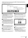
b DV IN/OUT connector (6-pin IEEE-1394)
This connector inputs and outputs digital video and audio
signals in DV format.
Notes
• If the unit is connected to a device equipped with a 6-pin
DV jack, when you intend to disconnect or reconnect the
DV cable, turn off the device and pull out the plug of its
power cord from the AC outlet beforehand. If you
connect or disconnect the DV cable while the device is
connected to the AC outlet, high-voltage current (8 to 40
V) is output from the DV jack of the device to this unit,
which may cause a malfunction.
• When connecting a device that has a 6-pin DV jack to
this unit, first connect the plug of the cable to the 6-pin
DV jack of the device.
• When searching at speeds in the range +
1
/
2
to +
1
/
30
or
−
1
/
30
to −
1
/
2
times normal speed, the audio signal output
from this connector and monitored on external
equipment may sound differently from the audio signal
played back on this unit.
c
cc
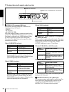
c REMOTE connector (D-sub 9-pin)
When controlling this unit from an editing control unit
such as the ES-7, PVE-500, BVE-600/800/910, or RM-
450/450CE, connect the editing control unit to this
connector using the optional 9-pin remote control cable.
d
dd
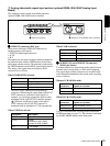
d REF. (reference) VIDEO IN connectors (BNC
type)
Input a reference video signal. The two connectors are
loop-through connectors. You can connect the reference
video signal input to the left connector to other equipment
via the right connector (marked ). When no connection
is made to the right connector, the left connector is
terminated with an impedance of 75 Ω automatically.
DV IN/OUT
REMOTE
AC IN
1/3
2/4
1/3
2/4
AUDIO IN
VIDEO
IN
Y/CPST R-Y/C B-Y
REF.VIDEO VIDEO OUT
AUDIO OUT
MONITOR
IN
IN OUT1 OUT2
Y/CPST
IN
INTC OUT
1/2 3/4 1/2 3/4
OUTAUDIO I/O (AES/EBU)
R-Y/C/CPST
(SUPER)
B-Y/CPST
SDI/SDTI
(QSDI)
a AC IN connector
b DV IN/OUT connector
A Analog video/audio signal
input section
(see page 25)
B Analog video/audio signal
output section
(see page 26)
C Digital signal input/output
section
(see page 27)
c REMOTE connector
D Time code input/output section
(see page 27)
d REF. VIDEO IN connectors