Chapter 1 Overview 11 (GB)
Chapter 1 Overview
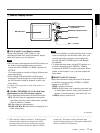
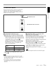
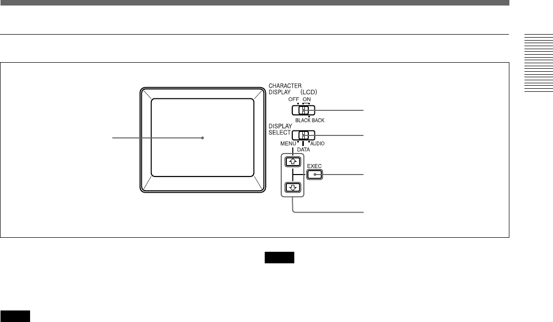
1 Monitor display section
1 LCD (Liquid Crystal Display) monitor
Displays the playback or EE
1)
pictures. Also,
superimposed time data, status information, menus,
audio level meters, etc. are displayed.
Notes
• The data items superimposed on the LCD monitor are
the same as items superimposed on a monitor
connected to the S VIDEO or VIDEO connectors in
OUTPUT.
You cannot make two monitors display different data
items individually.
• The backlight used in the built-in LCD monitor
deteriorates with prolonged use. If the brightness of
the LCD monitor cannot be adjusted, consult your
Sony dealer.
For details on the maintenance of the LCD monitor, see
page 74 (GB).
2 CHARACTER DISPLAY (LCD) (data items
superimposed on the LCD monitor) selector
Use to superimpose data items on the LCD monitor.
OFF: No data items are superimposed except the
tape label, title, data codes (camera data, and date/
time recorded by a camera).
ON: Data items are superimposed.
ON (BLACK BACK): Data items are displayed on a
black background.
Notes
• To choose whether or not the tape label, title, or data
codes are displayed, use the menu items. Also, you
can select the data code items to be displayed by
pressing the DATA CODE button on the Remote
Commander.
• To adjust the menu items, set the LCD monitor or a
monitor connected to the S VIDEO or VIDEO
connectors in OUTPUT to display the menu. When
neither of the monitors is set, you cannot adjust the
menu items.
3 DISPLAY SELECT selector
Selects the data items displayed on the LCD monitor
or a monitor connected to the S VIDEO or VIDEO
connectors in OUTPUT.
MENU: displays the menu.
DATA: displays time code, remaining tape time, type
of input signal selected, audio mode, presence or
absence of cassette memory, tape label, title, etc.
AUDIO: displays audio levels.
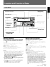
1 LCD monitor
2 CHARACTER DISPLAY
(LCD) selector
3 DISPLAY SELECT selector
4 EXEC button
.........................................................................................................................................................................................................
1) “EE” stands for “Electric to Electric.” In EE mode, the
video and audio signals that are input to the VCR’s
recording circuitry do not pass through any magnetic
conversion circuits but instead are output via electric
circuits only. This mode is used to check the input
signals and adjust input levels. The pictures output in EE
mode are referred to as EE pictures.
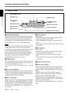
5 J / j buttons
(Continued)


