16 (GB) Chapter 1 Overview
Location and Function of Parts
Chapter 1 Overview
NTSC
PAL
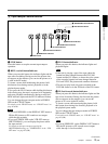
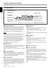
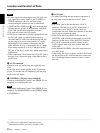
4 Display window
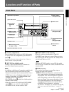
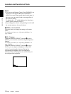
1 END SEARCH button
When you press this button, the unit searches the tape
and plays back the last five-second recorded picture.
After playback, the unit turns to the stop mode. Use
this function to record another image at the end of the
last recorded portion or to check the image itself.
Note
If you use a cassette without cassette memory, the end
search function does not work once you eject the
cassette after you have recorded on the tape. If you use
a cassette with cassette memory, the end search
function works even if you have ejected the cassette
one or more times. If there is a blank portion at the
beginning or between recorded portions, the end
search function may not work correctly.
2 INDEX button
Press this button during recording to mark an index. If
you mark an index at the scene you want to search for,
you can easily find the scene later.
For details on index, see “Recording Functions” on page 40
(GB).
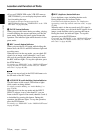
3 q (cassette) indicator
Lights when a digital video cassette is loaded. Even if
the unit is in the standby mode, the indicator lights as
long as a cassette is inside of the unit. While a cassette
is being ejected, the indicator flashes.
4 DVCAM indicator
Lights when the unit is playing back a tape recorded in
the DVCAM format. When REC MODE on the VTR
SET menu is set to DVCAM, this indicator also lights
during recording or when the unit is in the EE mode.
For details on the VTR SET menu, see “VTR SET menu” on
page 65 (GB).
5 NTSC indicator
Lights when:
• In the EE mode or during recording and the NTSC/
PAL select switch is set to NTSC.
•NTSC formatted video signals are input to the DV
jack.
•a tape that has NTSC formatted video signals is being
played back.
6 PAL indicator
Lights when:
• In the EE mode or during recording and the NTSC/
PAL select switch is set to PAL.
•PAL formatted video signals are input to the DV
jack.
•a tape that has PAL formatted video signals is being
played back.
7 Remote control detector
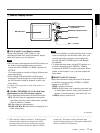
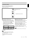
8 Time counter display
Displays time data (count value of the counter / time
code / user bits), the self-diagnostics code numbers
(page 75 (GB)), or the alarm messages (“Err” (page 72
(GB))).
When the count value of the counter is negative, “–”
appears as the first digit (leftmost digit). When that
value is positive, the first digit is blank.
When the format of the displayed time code is drop
frame mode, the drop frame indicator, located between
minutes and seconds, lights.
The user bits are displayed with periods (.) after each
digit.
2 INDEX button
6 PAL indicator
1 END SEARCH button
3 q (cassette)
indicator
4 DVCAM indicator
8 Time counter display
0 RESET button
5 NTSC indicator
9 COUNTER SELECT
selector
Drop frame indicator
7 Remote control detector


