


24 (GB) Chapter 1 Overview
Displaying Various Data
Chapter 1 Overview
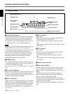
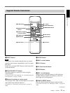
6 Index indicator
Displays INDEX MARK when an index has been
marked.
7 Caution indicator
Displays a caution.
For details on cautions, see “Alarm Messages” on page 72
(GB).
8 DVCAM/DV indicator
In the EE or recording mode, displays the recording
format selected in REC MODE on the VTR SET
menu. During playback, displays the recording format
of the picture.
9 Audio mode indicator
In the EE or recording mode, displays the audio mode
selected in AUDIO MODE on the AUDIO SET menu.
During playback or audio dubbing, displays the audio
mode recorded on the tape. When you input a signal to
the DV jack, displays the audio mode of that signal.
0 Input signal indicator
Displays the INPUT SELECT selector setting.
qa NS (Non standard) audio mode indicator
This item is shown when a tape recorded in the unlock
audio mode is played back or when an unlock mode
signal has been input to the DV jack. In EE mode,
when REC MODE in the VTR SET menu is set to DV
SP, this item is always shown.
For details on the unlock mode, see “Compatibility of
DVCAM and DV Format” on page 76 (GB).
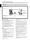
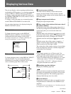
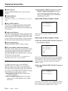
Audio screen
To display the audio screen, set the DISPLAY
SELECT selector to AUDIO. You can confirm or
adjust the audio levels on this screen. The display of
this screen changes depending on the audio mode and
the setting of the AUDIO OUTPUT SELECT selector.
The unit detects the audio mode as follows:
In the playback mode: Detects the audio mode
recorded on the tape.
In the recording/EE mode: Detects the selected
audio mode in AUDIO MODE on the AUDIO
SET menu.
When the INPUT SELECT selector is set to DV
and a DV signal is being input: Detects the
audio mode of the signals being input. (The
setting of AUDIO MODE on the AUDIO SET
menu becomes invalid.)
Audio mode: 48 kHz (2-channel, 16 bits)
–
∞
40 30 20 10 0
dB
CH1 ||||||||||||||||||·|··· ·
CH2 |||||||||||||||||·|···· ·
·· · · ··
(The levels of two channels, channels 1 and 2, are
displayed.)
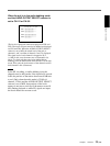
Audio mode: 32 kHz (4-channel, 12 bits)
(a)When the AUDIO OUTPUT SELECT selector is
set to CH-1/2 or CH-3/4
–
∞
40 30 20 10 0
dB
CH1 ||||||||||||||||||·|··· ·
CH2 |||||||||||||||||·|···· ·
CH3 | ·
CH4 | ·
·· · · ··
(The levels of four channels, channels 1 to 4, are displayed.
During playback, if the sounds are recorded onto channels 3
and 4, their levels meters will fluctuate. However, during
normal recording, you cannot record sounds onto the
channels 3 and 4.)
(b)When the AUDIO OUTPUT SELECT selector is
set to MIX
-∞
40 30 20 10 0
dB
·· ····
CH1 ⁄ 3 ||||||||||||||||||·|···
CH2 ⁄ 4 |||||||||||||||||·|····
(The mixed level of channels 1 and 3 is displayed on CH1/3;
that of channels 2 and 4 is displayed on CH2/4. The signal
level of each channel is dropped to 50% (–6 dB).)