


Setting the Time Code and User Bits
Chapter 3 Setting the Time Code
46 (GB) Chapter 3 Setting the Time Code
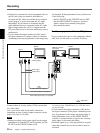
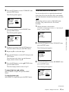
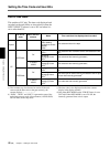
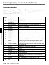
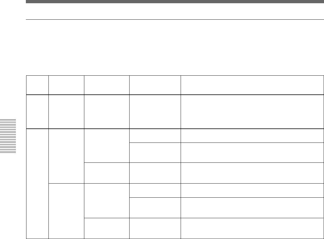
DSR-25 time codes
This unit has a DV jack. The time code displayed and
recorded on the tape differs as shown below when the
INPUT SELECT selector is set to DV and when it is
set to other than DV.
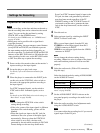
EE
INTERNAL
DV
S VIDEO
VIDEO
EXTERNAL
DV
S VIDEO
VIDEO
DV IN TC
menu
INPUT SELECT
selector
Mode
Time code/User bits displayed and recorded
Playback
Playback
Audio dubbing
Playback at various
speeds
a)
DUB1
b)
Time code/user bits on the tape
Duplicate
DUP1
b)
Time code/user bits of another device connected to the DV
jack
c)
Recording
Recording Pause
REC1
b)
Time code/user bits internally generated
c)
Recording
Recording Pause
REC1
b)
Time code/user bits internally generated
c)
Duplicate
DUP1
b)
Time code/user bits of another device connected to the DV
jack
Recording
Recording Pause
REC1
b)
Time code input of another device connected to the DV jack
and user bits internally generated
d)
Recording
Recording Pause
REC1
b)
Time code/user bits internally generated
c)
a) This includes stop, fast-forward or rewind. If the unit
cannot read the time code on the tape correctly, the
counter displays “– –:– –:– –:– –”.
b) “DUB1”, “DUP1” and “REC1” represent the state of the
unit when you press each of these buttons (AUDIO DUB,
DUP or REC) in the stop mode.
c) The time code is also displayed on the time counter
display in the display window.
d) Only when REC MODE on the VTR SET menu is set to
DVCAM. When REC MODE is set to DV SP, the
internally generated time code is output.