


14
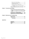
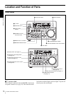
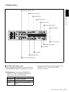
Location and Function of Parts
Chapter 1 Overview
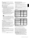
• When COMPOSITE/S VIDEO is selected:
• When Y
–R,B is selected:
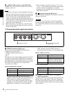
AUDIO indicators: Comprise the CH 1/2 indicator and
CH 3/4 indicator to indicate the channel selection for
analog audio output from the AUDIO OUT 1/3 and
AUDIO OUT 2/4 connectors.
You can change the channel selection with the AUDIO
OUTPUT menu item (see page 69).
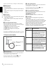
b INPUT signal display section
Indicates the input video and audio signal formats selected
with the INPUT SELECT buttons (i.LINK, VIDEO, CH1
1/2, and CH2 3/4 buttons).
i.LINK indicator: Lights when the digital video and audio
signals in i.LINK-compatible DV format are selected.
VIDEO indicators: The indicator (COMPOSITE, S
VIDEO, Y
−R,B, SDI, or SG) corresponding to the
selected input video signal format lights.
AUDIO indicators: Comprise the CH-1 1/2 indicator and
CH-2 3/4 indicator, under each of which there are four
more indicators (ANALOG, AES/EBU, SDI, and SG).
They indicate the selected input audio signal formats.
Note
The indicators blink if no signals are connected to the
selected video/audio input connectors.
c Time data type indicators
One of the three indicators (COUNTER, U-BIT, or TC)
lights to indicate the type of time data currently shown in
the time counter display.
COUNTER: Count value of the time counter
U-BIT: User bit data
TC: SMPTE time code (for DSR-DR1000A) or EBU time
code (for DSR-DR1000AP)
d DVCAM indicator
This stays lit.
e KEY INHI (key inhibit) indicator
Lights when the control mode selection switch is set to
KEY INHI.
f REC INHI (recording inhibit) indicator
Lights when the REC INHIBIT menu item (see page 62) is
set to ON.
g Disk end alarm indicator
Starts flashing when the remaining capacity of the disk is
for about 2 minutes.
h REPEAT (repeat playback) indicator
Lights when the REPEAT MODE menu item (see page
61) is set to ON to enable the repeat playback function.
i Time counter display
Indicates the count value of the time counter, time code,
VITC, or user bit data depending on the settings of the
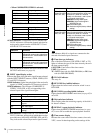
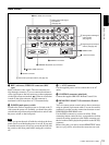
Connectors Output signals
Y/CPST Composite signal
R−Y/S−CS−C
B−Y/S−YS−Y
SUPER Composite signal
Connectors Output signals
Y/CPST Y signal
R−Y/S−CR−Y signal
B−Y/S−YB−Y signal
SUPER Composite signal
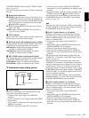
Indicators Functions
CH 1/2 Lights when channels 1 and 2 are
selected for analog audio output from
the AUDIO OUT 1/3 and AUDIO OUT
2/4 connectors
.
CH 3/4 Lights when channels 3 and 4 are
selected for analog audio output from
the AUDIO OUT 1/3 and AUDIO OUT
2/4 connectors
.
Indicators Meanings
COMPOSITE Composite video signal
S VIDEO S-video (separated Y and C) signals
Y−R,B Y, R−Y and B−Y component video
signals
SDI SDI video signal
SG Video test signal (factory default
setting)
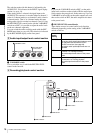
Indicators Functions
CH-1 1/2
(ANALOG, AES/
EBU, SDI, SG)
The indicator corresponding to the
signal format selected for audio input
to channel 1 (when in 2-channel
mode) or to channels 1 and 2 (when
in 4-channel mode) lights.
ANALOG: Analog audio signal
AES/EBU: Digital audio signal in
AES/EBU format
SDI: SDI audio signal
SG: Audio test signal (factory default
setting)
CH-2 3/4
(ANALOG, AES/
EBU, SDI, SG)
The indicator corresponding to the
signal format selected for audio input
to channel 2 (when in 2-channel
mode) or to channels 3 and 4 (when
in 4-channel mode) lights.
ANALOG: Analog audio signal
AES/EBU: Digital audio signal in
AES/EBU format
SDI: SDI audio signal
SG: Audio test signal (factory default
setting)