


77
Displaying Supplementary Status Information
Chapter 6 Menu Setting
Display format of supplementary status
information when the SUB STATUS menu
item is set to ALL
All items of supplementary status information are
displayed in the order shown below.
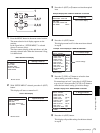
EXT LTC-T&U
[ELTU]
The internal time code generator is in
synchronization with the external time
code (LTC) input to the unit and is
generating the same time code value
and user bit value as those of the
external time code (regeneration).
EXT VITC-T&U
[EVTU]
The internal time code generator is in
synchronization with VITC present in
the external video signal input to the
unit and is generating the same time
code value and user bit value as
those of the external time code
(regeneration).
EXT DVIN-T&U
[EDTU]
The internal time code generator is in
synchronization with the external time
code input to the unit via the i.LINK
( S400(i.LINK)) interface and is
generating the same time code value
and user bit value as those of the
external time code (regeneration).
EXT DVIN. V-T&U
[EDTU]
The internal time code generator is in
synchronization with the external
VITC input to the unit via the i.LINK
( S400(i.LINK)) interface and is
generating the same time code value
and user bit value as those of the
external time code (regeneration).
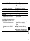
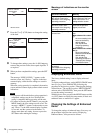
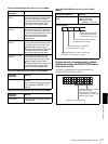
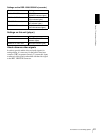
When the SUB STATUS menu item is set to REMAIN:
On-screen
indication
Meaning
REMAIN 184 min Remaining capacity of the disk in
minutes.
When the remaining capacity has not
been calculated, “REMAIN --- min”
appears.
When the SUB STATUS menu item is set to CLIP NAME:
On-screen
indication
Meaning
CLIP 00001 The name of the clip being recorded
or played back.
When the SUB STATUS menu item is set to TC MODE:
On-screen
indication
Meaning
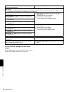
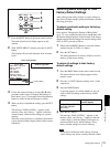
When the SUB STATUS menu item is set to AUDIO
MIXING:
On-screen indication Meaning
1 2 3 4
[MIX]
Input audio channels
selected for mixing
1 2 3 4: Input audio
channels 1, 2, 3 and 4
122334
Input audio channels 3 and
4 are mixed and recorded
on audio channel 4 on tape.
Input audio channel 3 is recorded
on audio channel 3 on tape.
Input audio channel 2 is recorded
on audio channel 2 on tape.
Input audio channels 1 and 2 are mixed and
recorded on audio channel 1 on tape.
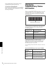
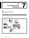
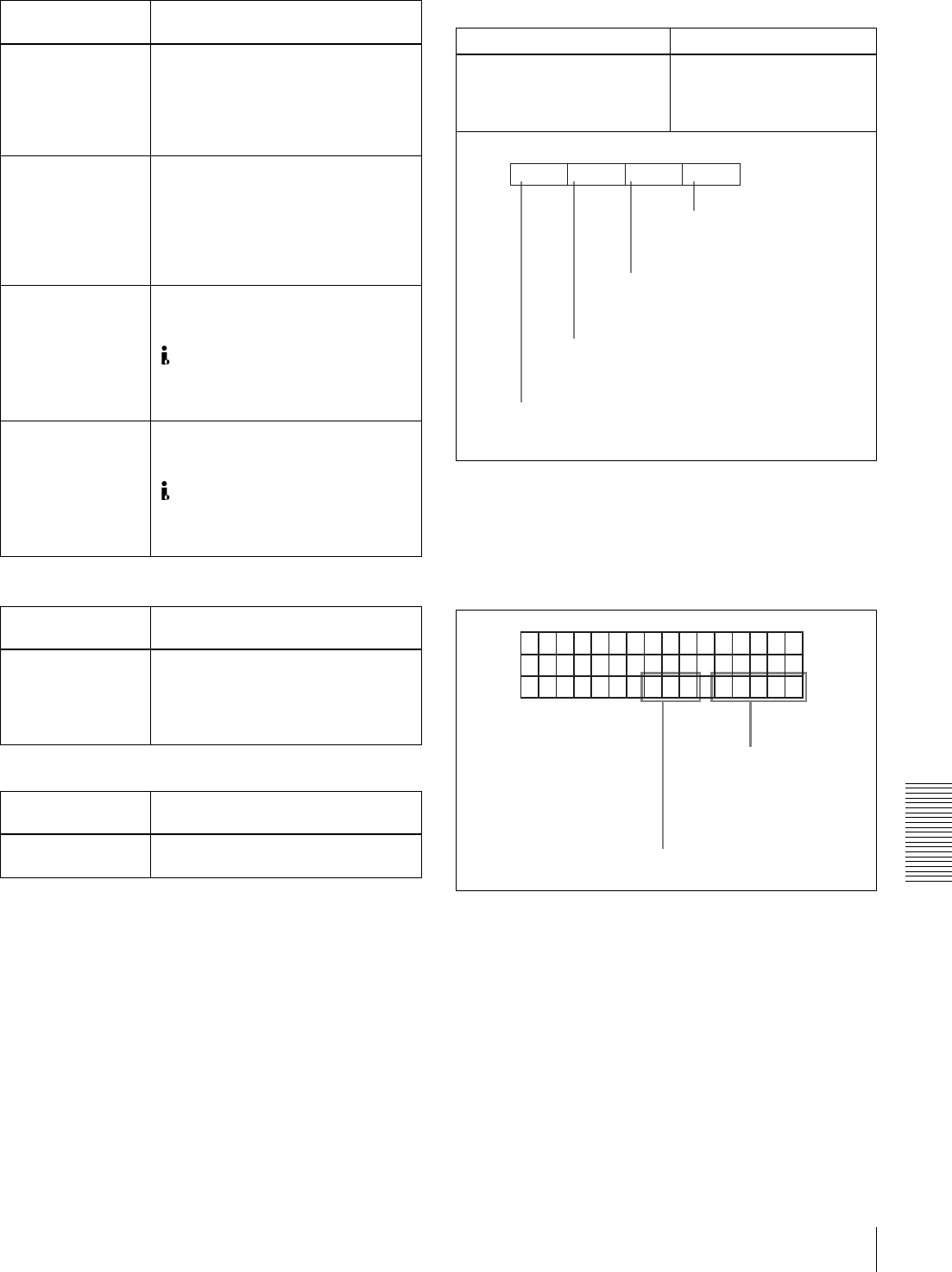
Example display:
TCR
PLA
Y
00:04 47
:
07
LOCK
.
VMI E
X
TU
D
Setting for input audio mixing
Operating mode of the internal
time code generator
(The rightmost “V” appears
when the VITC menu item (see
page 65) is set to ON.)