


66
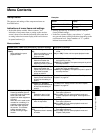
Menu Contents
Chapter 6 Menu Setting
VITC POS SEL-1 [> VITC pos-1]: Select a line to insert the
VITC in.
Note
You can insert the VITC signal in two places. To insert it in two
places, set both this item and also VITC POS SEL-2.
(For DSR-DR1000A)
20 LINE [>> 20 line] to 12 LINE [>> 12 line]: Select any line
from 12 to 20.
Factory default setting: 16 LINE [>> 16 line]
(For DSR-DR1000AP)
22 LINE [>> 22 line] to 9 LINE [>> 9 line]: Select any line
from 9 to 22.
Factory default setting: 19 LINE [>> 19 line]
VITC POS SEL-2 [> VITC pos-2]: Select a line to insert the
VITC in.
Note
You can insert the VITC signal in two places. To insert it in two
places, set both this item and also VITC POS SEL-1.
(For DSR-DR1000A)
20 LINE [>> 20 line] to 12 LINE [>> 12 line]: Select any line
from 12 to 20.
Factory default setting: 18 LINE [>> 18 line]
(For DSR-DR1000AP)
22 LINE [>> 22 line] to 9 LINE [>> 9 line]: Select any line
from 9 to 22.
Factory default setting: 21 LINE [>> 21 line]
VITC OUTPUT [> VITC out]: Select the time code to be output
as VITC.
OFF [>> OFF]: Do not output VITC.
TC [>> TC]: Output TC after converting it into VITC.
*VITC [>> VITC]: Output VITC.
EE OUT PHASE [> EE out]: Determine the output phase for
the LTC signal output from the TIME CODE OUT
connector when recording time code and in STOP REC
mode (forced EE mode).
*MUTE [>> mute]: Mute the output.
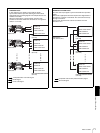
THROUGH [>> through]: Output the time code input to the
TIME CODE IN connector as it is. (See example
configuration on page 71.)
VIDEO INPUT PHASE [>> V input]: Output the time code
with the same phase as the input video signal phase.
(See example configuration on page 71.)
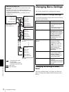
VIDEO OUTPUT PHASE [>> V output]: Output the time code
with the same phase as the output video signal phase.
(See example configuration on page 72.)
MUTE IN SRCH [> Mute in SR]: Select whether to mute the
output from the TC OUT connector in search (jog/shuttle)
mode.
OFF [>> OFF]: Do not mute.
*ON [>> ON]: Mute.
VIDEO CONTROL [Video]: Settings related to video control Description of settings
INT VIDEO SG [> Video SG]: Select the test signal to be
output from the internal test signal generator. When SG is
selected using the VIDEO button in the video/audio input
setting section, the internal test signal generator outputs
the selected test signal. This signal can be recorded.
(For DSR-DR1000A)
*75% COLOR BARS [>> 75% bars]: 75% color bar signal
BLACK BURST [>> BB]: Black burst signal
(For DSR-DR1000AP)
*100% COLOR BARS [>> 100% bars]: 100% color bar signal
75% COLOR BARS [>> 75% bars]: 75% color bar signal
BLACK BURST [>> BB]: Black burst signal
STD/NON-STD [> STD/N-STD]: Select the STD or NON-STD
mode in accordance with the composite video or S-video
input.
*FORCED STD [>> STD]: The STD mode is always used
(forced STD mode).
FORCED NON-STD [>> NON-STD]: Use this setting when
the input video signal is unstable (forced NON-STD
mode).
OUT REF SEL [> Out Ref]: Select the reference video signal
to use.
*REF VIDEO [>> REF]: Use the signal input to a REF. VIDEO
IN connector as the reference video signal. The input
video signal to be edited is required to be in
synchronization with the reference video signal.
INPUT VIDEO [>> INPUT]: Use the input video signal
selected with the VIDEO button in the video/audio input
setting section.
(For DSR-DR1000A only)
SETUP REMOVE [> Setup rmv]: Determine whether or not to
remove black setup (7.5 IRE) from input analog video
signals when converting them into digital signals.
*OFF [>> OFF]: Do not remove black setup.
ON (REMOVE) [>> ON]: Remove black setup.
TIME CODE [Time code]: Settings related to the time code
generator
Description of settings