


20
Location and Function of Parts
Chapter 1 Overview
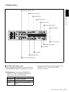
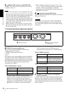
f S400 (i.LINK) connector (6-pin IEEE-1394)
Connect a DV cable to make connections to DV devices,
computers, and so on.
Notes
• If the unit is connected to a device equipped with a 6-pin
DV jack, when you intend to disconnect or reconnect the
DV cable, turn off the device and pull out the plug of its
power cord from the AC outlet beforehand. If you
connect or disconnect the DV cable while the device is
connected to the AC outlet, high-voltage current (8 to 40
V) is output from the DV jack of the device to this unit,
which may cause a malfunction.
• When connecting a device that has a 6-pin DV jack to
this unit, first connect the plug of the cable to the 6-pin
DV jack of the device.
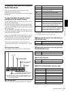
• When searching at speeds in the range +
1
/
2
to +
1
/
30
or
−
1
/
30
to −
1
/
2
times normal speed, the audio signal output
from this connector and monitored on external
equipment may sound differently from the audio signal
played back on this unit.
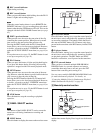
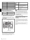
g (network) connector (RJ-45 type)
This is a 10BASE-T/100BASE-TX connector for network
(Ethernet) connection.
CAUTION
For safety, do not connect the connector for peripheral
device wiring that might have excessive voltage to this
port. Follow the instructions in this manual when making
connections.
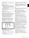
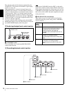
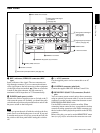
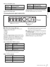
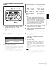
1 Analog video/audio signal input section
a VIDEO IN connectors (BNC type)
There are the following VIDEO IN connectors for
inputting analog video signals:
• Y/CPST (loop-through connectors)
•R
−Y/C
•B
−Y
The signals you can connect to these connectors depend on
the selection made with the VIDEO button in the video/
audio input selection section. The selection is indicated by
the VIDEO indicators in the INPUT signal display section.
The analog video signals that can be input to these
connectors are as follows.
When COMPOSITE is selected:
The two Y/CPST connectors are loop-through
connectors. When using the signal input to the left Y/
CPST connector as a reference video signal, for
example, you can bridge-connect the signal to other
equipment via the right Y/CPST connector (marked
). When no connection is made to the right Y/
CPST connector, the left Y/CPST connector is
terminated with an impedance of 75 Ω automatically.
When S VIDEO is selected:
When Y
–R,B is selected:
b AUDIO IN 1/3 and AUDIO IN 2/4 connectors
(XLR-3 pin, female)
Use these connectors to input analog audio signals from an
external video cassette player or other audio equipment.
The signals input to these connectors are recorded on the
audio channels determined by the current audio recording
mode, as follows.
VIDEO IN
Y/CPST
R-Y/C
B-Y
1/3 2/4
AUDIO IN
1 VIDEO IN connectors
2 AUDIO IN 1/3 and AUDIO IN
2/4 connectors
Connectors Input signals
Y/CPST Composite signal
R−Y/C — (not usable)
B−Y — (not usable)
Connectors Input signals
Y/CPST Y signal
R−Y/C C signal
(3.58 MHz for DSR-DR1000A/
4.43 MHz for DSR-DR1000AP)
B−Y — (not usable)
Connectors Input signals
Y/CPST Y signal
R−Y/C R−Y signal
B−YB−Y signal