


English
7
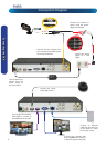
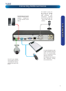
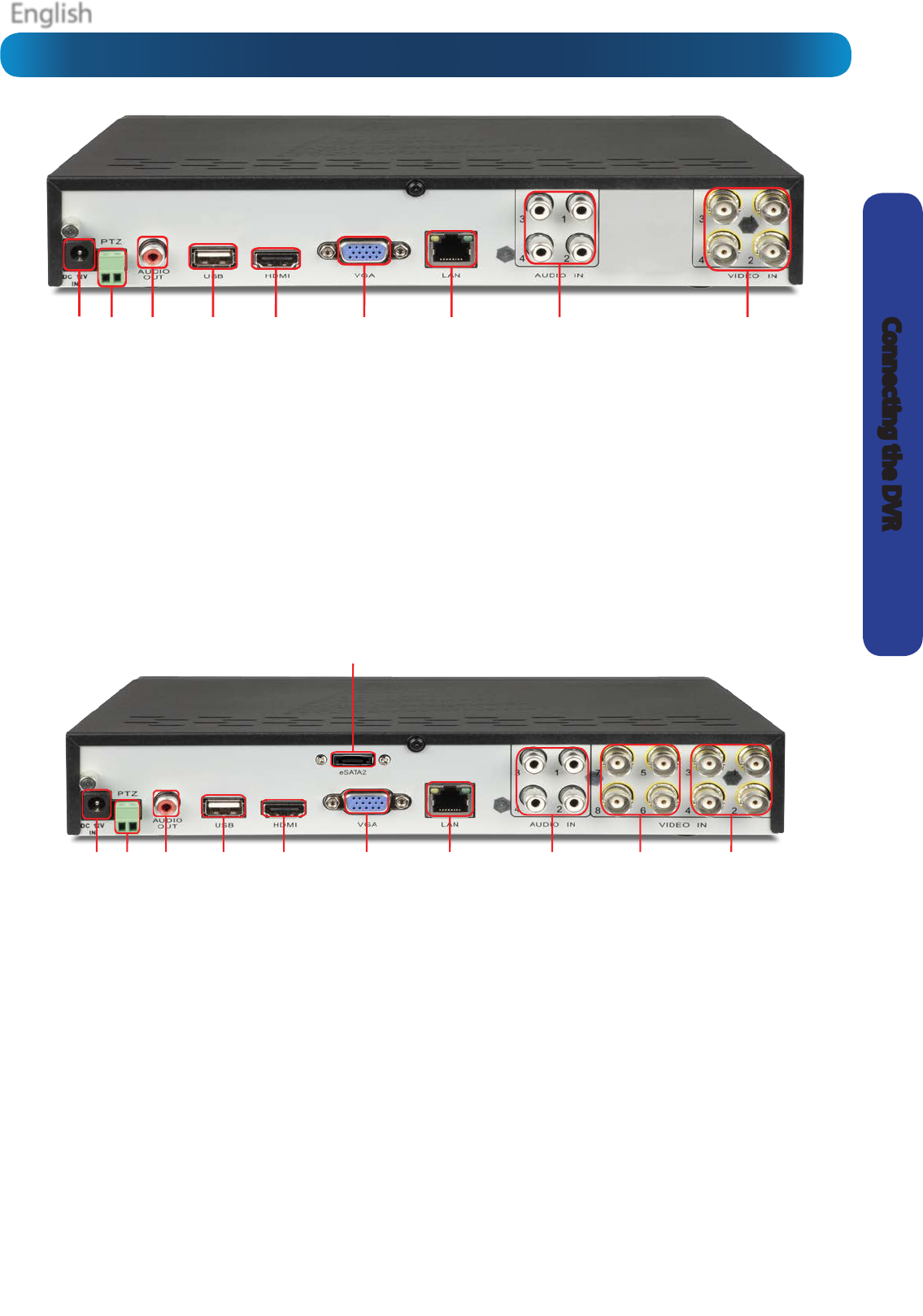
Connecting the DVR
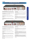
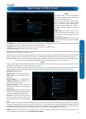
The Rear Panel of the DVR
1 2 3 4 5 6 7 8 9
1 2 3 4 5
6
7 8 9 10 11
4-CH DVR
8-CH DVR
1) DC 12V Power Input: Where you connect the included
DC 12V power adapter. Use only the supplied power adapter
with the DVR, and use the power adapter only with the DVR.
2) PTZ (RS485) Port: To connect the RS485 cables to control
a PTZ (pan, tilt, zoom) device to the DVR.
3) Audio Output: A standard line-level audio output.
4) USB 2.0 Port: For connecting a USB mouse or a USB stor-
age device.
5) HDMI Output: The primary output of the DVR. For the
highest possible video output quality, we suggest using this
output.
6) VGA Output: For connecting a television or PC monitor
with a VGA input.
7) Network Port: Where you can connect the DVR to a net-
work, typically directly into the router or network switch.
8) Audio Inputs: These will accept a standard line-level
signal (<1V).
9) Video Inputs 1 - 4: These are your primary video inputs.
Each accepts a standard composite video signal and con-
nects via a BNC connector. The channels are labelled by
number in the same order as they will appear on your DVR’s
interface.
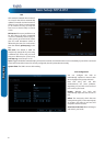
1) DC 12V Power Input: Where you connect the included
DC 12V power adapter. Use only the supplied power adapter
with the DVR, and use the power adapter only with the DVR.
2) PTZ (RS485) Port: To connect the RS485 cables to control
a PTZ (pan, tilt, zoom) device to the DVR.
3) Audio Output: A standard line-level audio output.
4) USB 2.0 Port: For connecting a USB mouse or a USB stor-
age device.
5) HDMI Output: The primary output of the DVR. For the
highest possible video output quality, we suggest using this
output.
6) eSATA Port: To connect an external hard drive which
will act as a live recording drive in the same manner as the
installed HDD.
7) VGA Output: For connecting a television or PC monitor
with a VGA input.
8) Network Port: Where you can connect the DVR to a net-
work, typically directly into the router or network switch.
9) Audio Inputs: These will accept a standard line-level
signal (<1V).
10) Video Inputs 5 - 8 (8-CH only): These are your second-
ary video inputs. Each accepts a standard composite video
signal and connects via a BNC connector. The channels are
labelled by number in the same order as they will appear on
your DVR’s interface.
11) Video Inputs 1 - 4: These are your primary video inputs.
Each accepts a standard composite video signal and con-
nects via a BNC connector. The channels are labelled by
number in the same order as they will appear on your DVR’s
interface.
Note: Only the 1425 & 1450 DVR models have the eSATA
port available.