


6 F 3 B 0 3 6 4
101
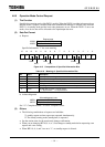
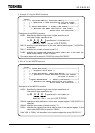
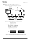
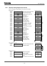
5.2.2 Configuration of a Module Setting Sample Program
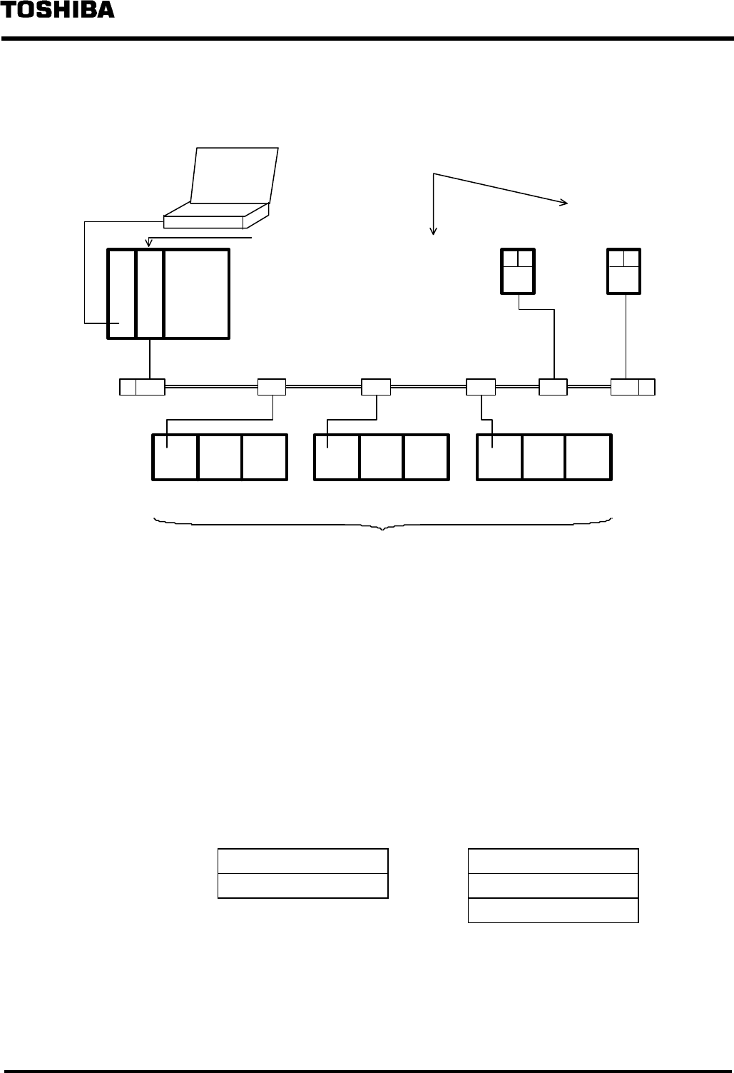
The figure below is the configuration of a module setting sample program.
D
N
2
1
1
T
2
E
T
−
PDS
Bit strobe mode slave device
Installed in slot 1
Photoelectric switch
NA : 8
Photoelectric switch
NA : 22
Polling Mode Device
NA : 0
AD DO DIAD DO DIAD DO DI
Remote I/O
NA : 6
Remote I/O
NA : 1
Remote I/O
NA : 20
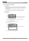
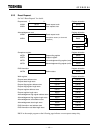
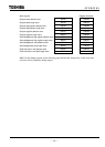
Photoelectric switch: Series 9000 photoelectric sensor (Rockwell Automation)
Bit strobe mode slave device
Reception data size: 1 byte
Remote I/O:FLEX I/O (Rockwell Automation)
Polling mode slave device
AD: 1794-ADN...FLEX - I/O adapter module
DO: 1794-OB16...24 Vdc, 16-point DO module
DI: 1794-IB16...24 Vdc, 16-point DI module
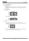
Transmitting data size: 4 bytes (2 words)
Reception data size: 6 bytes (3 words)
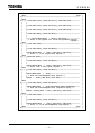
Transmission data Reception data
A Output data to DO B Input data from AD
A + 1 Output data to DI B + 1 Input data from DO
B + 2 Input data from DI
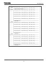
* Refer to the instruction manual made by Rockwell Automation for details about Series 9000
photoelectric sensors and FLEX I/O.