


6 F 3 B 0 3 6 4
121
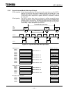
5.3 Slave Data Input/Output
After the DN211 is set to "run mode" by operation mode control request, the ladder program for the
T2/T2E/T2N writes data to output slave devices and also reads data inputted from slave devices as
well. As described in "1.4 The Basic Functions," the communication between the DN211 and slave
devices can be performed with the polling instruction/response mode and bit strobe
instruction/response mode. In addition, synchronous mode or asynchronous mode can be used to
exchange data between the T2/T2E/T2N and the DN211.
This section describes data input/output between the T2/T2E/T2N and the DN211 in
synchronous mode or asynchronous mode.
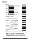
5.3.1 Slave Device Check
It is recommended to check the communication circuits with the slave devices before
reading/writing slave input/output data. This can be done when you check for MS/NS's green
lighting on the front panel and for the local node address indication on the 7-segment LED. This
checking also can be done through the program when you find the number of the total
devices (029EH) and the number of the online devices (029DH) in the RAS information
are equal. Moreover, when a difference is found in the numbers of the total devices and of the
online devices, no-responded slave devices can be identified using the polling no-responded device
map and the bit strobe no-responded device map.
The sample program in this chapter checks communication circuits by comparing the number of the
total devices with the number of the online devices; and when these numbers differ, the program
will stop data updates.
• The number of total devices(029EH):
Indicates the number of the slave devices specified by a parameter setting request (setting
information).
• The number of online devices(029DH):
Indicates the number of the slave devices which are performing data input/output with the
DN211 (execution information).
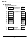
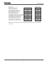
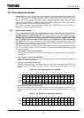
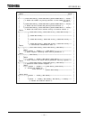
• Polling no-responded device map
Indicates, per bit per device, the number of the slave devices not responded to the DN211 (No
response for ON). The figure in frames in Table 5.2 represent the node address of a slave
device.
Table 5.2 Polling No-response Slave Devices
F E D C B A 9 8 7 6 5 4 3 2 1 0
0297H 15 14 13 12 11 10 9 8 7 6 5 4 3 2 1 0
0298H 31 30 29 28 27 26 25 24 23 22 21 20 19 18 17 16
0299H 47 46 45 44 43 42 41 40 39 38 37 36 35 34 33 32
029AH 63 62 61 60 59 58 57 56 55 54 53 52 51 50 49 48
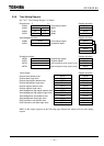
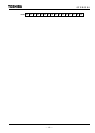
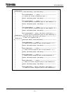
• Bit strobe no-responded device map
Indicates, per bit per device, the number of the slave devices not responded to the DN211 (No
response for ON). The figure in frames in Table 5.3 represents the node address of a slave
device.
Table 5.3 Bit Strobe No-response Slave Devices
F E D C B A 9 8 7 6 5 4 3 2 1 0
0293H 15 14 13 12 11 10 9 8 7 6 5 4 3 2 1 0
0294H 31 30 29 28 27 26 25 24 23 22 21 20 19 18 17 16
0295H 47 46 45 44 43 42 41 40 39 38 37 36 35 34 33 32