


6 F 3 B 0 3 6 4
43
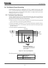
3.4 Connection with the Network
This section describes how to connect the DeviceNet cable to the DN211.
CAUTION
1. Do not engage in attaching or detaching the DeviceNet cable with network side
connector during network operation. Failing to do so can cause reverse connection
or short circuit of the network power, resulting in no communication with other nodes.
2. When you connect the DeviceNet cable with the network side connector, be sure not
to make the wrong connection. Failing to do so can cause short circuit of the network
power, resulting in no communication with other nodes.
3. Neither attach nor detach the network side connector with the device side connector
on the DN211 front panel while the T2/T2E/T2N is rising just after the power is turned
ON. Failing to do so can cause the DN211 to fail or malfunction.
4. Attaching the opposite end of the network side connector with/from a device side
connector is not possible because of the specific form. Trying connecting the wrong
end by excessive force can damage both the network side connector and the device
side connector.
5. Be sure not to wire the cable in too tightly stretched state or in bent state.Also, don't
put heavy stuff on the cable. Otherwise, the cable could break.
6. Ask the qualified expert for the installation work of the DeviceNet cables because it
requires sufficient safety and noise-suppression measures.
Refer to DeviceNet Volume I, Release 1.3, for the standard installation.
Also see "8.4 Network Installation" in this manual.
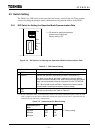
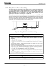
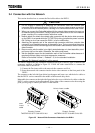
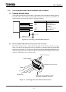
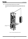
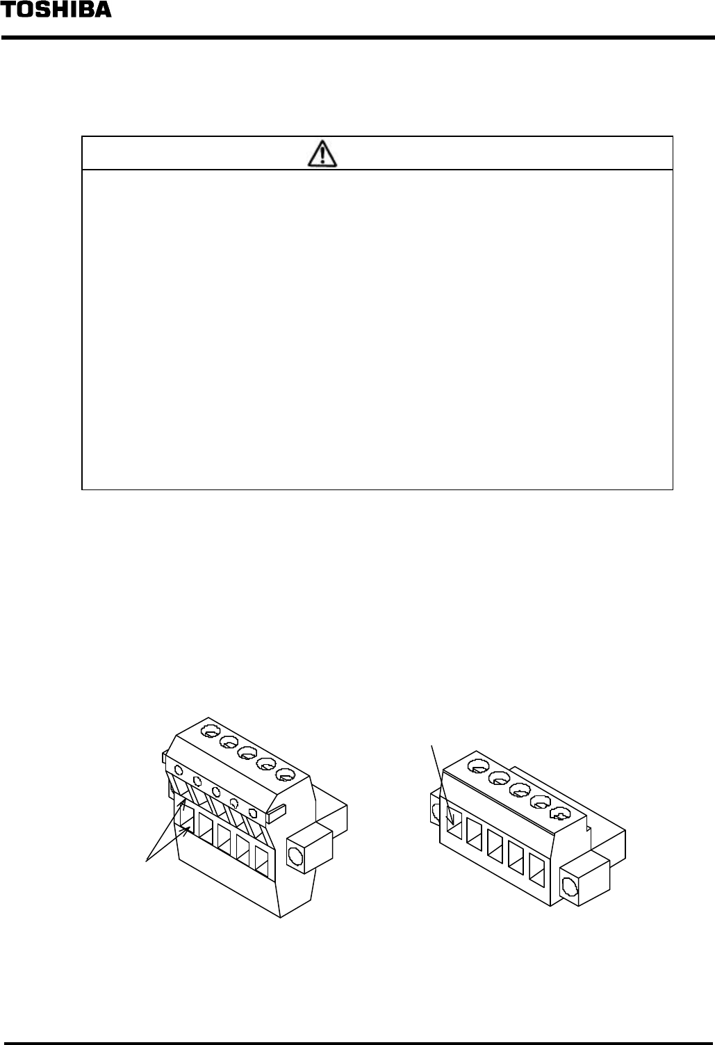
The DN211 supports the plug connection connector(open type). It has two types of network side
connectors attached, as shown in Figure 3.5. Follow the order stated below to connect the
DeviceNet cable to the DN211.
1) Connect the Devicenet cable to the network side connector and fix it.
2) Insert the network side connector into the device side connector on the front panel of the
DN211.
The connector at the left-side figure below has the upper and lower rows with holes for cables so
that the DN211 can be connected in the middle of the network daisy chain.
Meanwhile, the connector at the right-side figure below has a row with holes for cables so that the
DN211 can be connected at the network end. Select either of the connectors after discussing the
point you are going to connect your DN211 in the network.
Phoenix Contact
TMSTBP2.5/5-STF-5.08 AB GY AU
Phoenix Contact
MSTBP2.5/5-STF-5.08 AB GY AU SO
Figure 3.5 Network Side Connectors Attached to the DN211
Hole to
insert a
cable
Hole to insert a cable