


6 F 3 B 0 3 6 4
12
Usage Recommendations
This section puts together the knowledge and handling manners necessary for correct operation.
Read the section carefully and be familiar with equipment knowledge, safety information, and
notes.
•
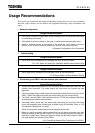
Network cnfiguration
Usage Recommendation
1. Don't make a network configuration whose extended trunk line and drop lines have
no node being connected.
2. Don't attach a terminal resistor to the node. It could cause communication error.
3. Attach a terminal resistor to both ends of the trunk line; don't attach a terminal
resistor on the end of a drop line. Attach only to both ends of the trunk line.
1.2 Network Configuration of the DeviceNet
•
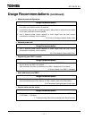
Switch setting
Usage Recommendation
1. Use a small minus screwdriver for changing the value of the DIP switch.
3.2.1 DIP Switch for Setting the Operation Mode/Communication Rate
Usage Recommendation
1. Use a small minus screwdriver for changing values of the rotary switch.
3.2.2 Rotary Switch for Node Address Setting
•
Connecting your DN211 with the network side connector
Usage Recommendation
1. Loosen the cable fixing screws on the connector before inserting a cable into the
network side connector. The cable cannot be fixed when the screws are kept
tightened.
2. Colors corresponding to cable colors are printed by the device side connector of the
DN211. Match the cable colors with the printed colors to have correct wiring.
3. The DN211 and the DN311 (DeviceNet module for T3/T3H) have different directions
for attaching the network side connector.
4. DeviceNet cable, power tap, and device tap (connecting the trunk line with drop
lines) are necessary when constructing a system using a DeviceNet. Refer to "3.6
The Network Components" for detail.
Some of the network components must be prepared by the user.
5. When you use the network side connector that has the upper and lower rows with
holes for cables (at the left-side Figure 3.5), the connector protrudes from the left-
side DN211 about 5mm. When you attach or detach the left-side module of DN211,
you must detach the connector from DN211.
3.4.2 Connecting Network Side Connector to the DN211