


6 F 3 B 0 3 6 4
52
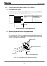
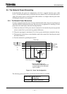
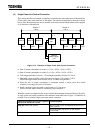
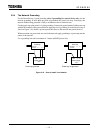
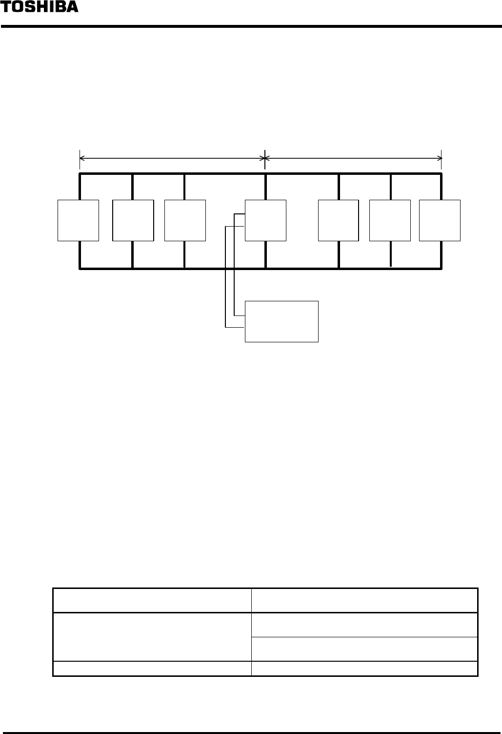
(4) Single Power Unit Central Connection
This section describes an example of installing a network power unit at the center of the trunk line
(Thick cable) with a total extension of 240 meters. The current consumption by the node is shown
below. Since the network power unit is installed at the center, the maximum current can be supplied
to all directions of the network.
Node 6Node 5Node 4Node 1Node 2Node 3
Network
power-supply
unit
Power
tap
Section 1
120 m
V
+−
0.1A 0.25A 0.2A V
−
0.15A 0.25A 0.15A
Section 2
120 m
Figure 3.13 Example of Single Power Unit Central Connection
a) Sum of current consumption in section 1 = 0.1A + 0.25A + 0.2A = 0.55A
a') Sum of current consumption in section 2 = 0.15A + 0.25A + 0.15A = 0.55A
b) Total length extended in section 1 = Total length extended in Section 2 = 120 m
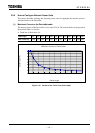
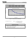
c) Maximum current available on the cable based on Figure 3.10 = approx. 2.56 A
(Obtain the approximate value between 100 to 150 meter straight cable.)
d) Since the sum of current consumption < maximum current, a single power unit central
connection can supply the power to all nodes.
e) Install a network power unit with a rated current of 1.1A or more.
(Select one with ample current in considering usage conditions.)
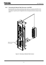
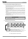
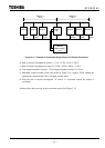
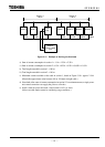
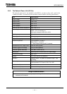
When the current consumption by the section exceeds the maximum current available for the cable
in single power unit central connection, take measures in the table below. Figure 3.14 indicates an
example of an overloaded single power unit central connection.
Cable section where the current is applied
beyond the maximum current
Countermeasure
Only one of the two section Move a node in the overloaded section to the
other section.
Move the power tap closer to the section
overloaded.
Both sections Use two power taps.