


6 F 3 B 0 3 6 4
47
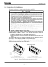
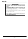
Usage Recommendation
1. Loosen the cable fixing screw on the connector before inserting cables into the
network side connector. The cable cannot be fixed when the screws are kept
tightened.
2. Colors corresponding to cable colors are printed by the device side connector of the
DN211. Match the cable colors with the printed colors to have correct wiring.
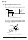
3. The DN211 and the DN311 (DeviceNet module for the T3/T3H) have different
directions for attaching the network side connector.
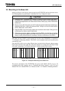
4. DeviceNet cables, power tap, and device tap (connecting the trunk line with drop
lines) are necessary when constructing a system using a DeviceNet. Refer to "3.6
The Network Components" for detail.
Some of the network components must be prepared by the user.
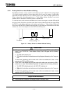
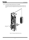
5. When you use the network side connector that has the upper and lower rows with
holes for cables (at the left-side Figure 3.5), the connector protrudes from the left-
side DN211 about 5mm. When you attach or detach the left-side module of DN211,
you must detach the connector from DN211.