


6 F 3 B 0 3 6 4
133
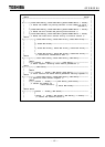
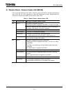
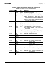
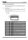
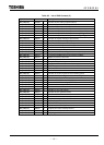
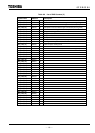
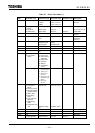
Table 6. 3 Combined Indications of the 7
-
Segment LED and 2
-
Color LED
M: DN211 node address S: Slave device node address
7
-
segment LED MS NS Description
78 ⇔ S Green
lighting
Red
blinking
When unable to start communicating with one or more
slave devices in the scan list
79 ⇔ M Green
lighting
Red
blinking
1) When the "START" bit was not set to "1" at run
request (followed by the indication of 78 ⇔ S )
2) When response from all slaves ceased during
normal transmission (followed by the indication of 72
⇔ S )
3) No slave device is found in network when starting
transmission (this display only)
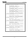
84 ⇔ M Green
lighting
Green
blinking
When the slave devices were not initialized
91 ⇔ M Green
lighting
Red
lighting
When busoff occurred (communication halt was
chosen when busoff occurred)
92 ⇔ M Green
lighting
Not lit 1) No network power is supplied to the 1DN211.
2) The network connector on the DN211 was
disconnected.
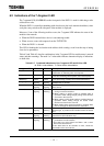
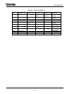
A0 - CA Irregular Irregular When requests to the T2/T2E/T2N are completed
unsuccessfully, completion status (Table 4.17) is
indicated on the 7-segment LED.
F0 ⇔ M Red
lighting
Not lit Down mode: Watchdog timeout error
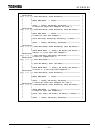
F1 ⇔ M Red
blinking
Not lit Down mode: Memory bus trouble occurred
F2 ⇔ M Red
blinking
Not lit Down mode: TRAP occurred
F3 ⇔ M Red
lighting
Not lit Down mode: BCC check error occurred on ROM
(at DN211 startup)
F4 ⇔ M Red
lighting
Not lit Down mode: Read/write error occurred on RAM
(at DN211 startup)
F5 ⇔ M Red
lighting
Not lit Down mode: Read/write error occurred on the
T2/T2E/T2N communication memory at
DN211 startup
F6 ⇔ M Red
blinking
Not lit Down mode: DN211 node address setting abnormal
F7 ⇔ M Red
blinking
Not lit Down mode: DN211 network communication rate
setting abnormal
F8 ⇔ M Red
blinking
Not lit Down mode: EEPROM for scan list read error
occurred