


6 F 3 B 0 3 6 4
64
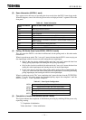
(1) Input Data Semaphore Register (0106H: 1 word)
This semaphore register is used when inputting data into the T2/T2E/T2N from the DN211
(effective only for synchronous transmission mode). The register is used both in the polling mode /
bit strobe mode.
• DN211 side operation
The DN211 writes data, collected from the slave devices in the polling mode or the bit strobe
mode, into "polling / bit strobe input data area" before setting "1" to this register.
• T2/T2E/T2N ladder program operation
The ladder program for the T2/T2E/T2N monitors this register. When detecting "1" is written
into this register, the ladder program reads data from the "polling / bit strobe input data area" and
then writes "0" in the register before notifying the DN211 of read completion.
Write the value "0" only in this semaphore register.
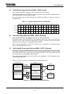
(2) Polling Output Data Semaphore Register (0105H: 1 word)
This semaphore register is used when outputting polling data to the DN211 from the T2/T2E/T2N
(effective only for synchronous transmission mode).
• T2/T2E/T2N ladder program operation
The ladder program writes data, to be outputted to the "polling output data area," to slave device
in the polling mode before writing "1" in this register, and then instructs the DN211 to start
output.
Write the value "1" only in this semaphore register.
• DN211 side operation
The DN211 monitors this register in the "scan interval wait time" cycle specified from the
T2/T2E/T2N. When detecting "1" is set to this register, the DN211 outputs output data in the
"polling output data area" to slave devices. When the output is completed, "0" is set to the
register. The "scan interval wait time" is explained in "4.6.3 Parameter Setting Request (local
node)."
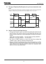
(3) Bit Strobe Output Data Semaphore Register (0104H: 1 word)
This semaphore register is used when outputting bit strobe data to the DN211 from the
T2/T2E/T2N (effective only for synchronous transmission mode).
• T2/T2E/T2N ladder program operation
The ladder program writes data, to be outputted to slave devices in the bit strobe mode, into the
"bit strobe output data area" before writing "1" into this register, and then instructs the DN211 to
start output.
Write the value "1" only in this semaphore register.
• DN211 side operation
The DN211 monitors this register in the "scan interval wait time" cycle specified from the
T2/T2E/T2N. When detecting "1" is set to this register, the DN211 outputs output data in the "bit
strobe output data area" to slave devices. When the output is completed, "0" is set to the register.
The "scan interval wait time" is explained in "4.6.3 Parameter Setting Request (local node)."