


15
Chapter 2: Connecting your TV
Copyright © 2005 TOSHIBA CORPORATION. All rights reserved.
(E) 42/50HPX95 *web 213:276
IN from ANT
VIDEO AUDIO
OUT to TV
CH 3
LR
LR
CH 4
IN
OUT
OUT
OUT
IN
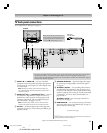
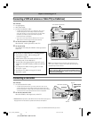
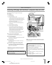
Signal splitter
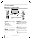
You will need:
one signal splitter
three coaxial cables
two sets of standard A/V cables
• For better picture performance, if your VCR has S-video, use an
S-video cable (plus the audio cables) instead of the standard
video cable. However, do not connect both types of video cables
to VIDEO 1 (or VIDEO 2) at the same time or the picture
performance will be unacceptable.
• If you have a mono VCR, connect L/MONO on the TV to your
VCR’s audio out terminal using the white audio cable only.
To view the antenna or Cable signal:
Select the ANT 1 video input source on the TV.*
To view the VCR:
Turn ON the VCR. Select the VIDEO 1 video input source
on the TV.*
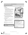
Connecting a VCR and antenna or Cable TV (no Cable box)
From Cable TV or antenna
Stereo VCR
The unauthorized recording, use, distribution, or revision of television
programs, videotapes, DVDs, and other materials is prohibited under the
Copyright Laws of the United States and other countries, and may subject
you to civil and criminal liability.
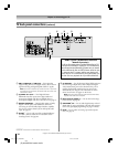
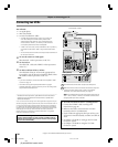
To use the TV Guide On Screen
™
recording features:
1. Connect the G-LINK
™
cable according to the
instructions on page 28.
2. Make sure the VCR is connected to the A/V OUT
terminals on the TV (see illustration).
3. Set the VCR to the appropriate line input (refer to your
VCR owner’s manual for details), and then turn OFF the
VCR.
4. See Chapter 5 for details on setting up the TV Guide
On Screen
™
system.
5. See Chapter 7 for details on using the TV Guide
On Screen
™
system.
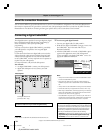
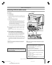
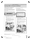
Connecting a camcorder
You will need:
one set of standard A/V cables
• For better picture performance, if your camcorder has S-video, use an
S-video cable (plus the audio cables) instead of the standard video cable.
Do not connect both an S-video cable and a standard video cable to VIDEO
3 at the same time or the picture performance will be unacceptable.
To view the camcorder video:
Select the VIDEO 3 video input source on the TV.*
VIDEO 3 inputs
on TV left side
panel
Camcorder
______________
* To select the video input source, press INPUT on the remote control (see page 72).
To program the TV remote control to operate other devices, see Chapter 3.
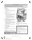
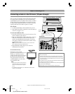
Note: The VIDEO/AUDIO OUT terminals output signals from the
ANT 1, ANT 2, VIDEO 1, VIDEO 2, and VIDEO 3 terminals when the
appropriate input mode is selected.
VIDEO
AUDIO
OUT
L
R
TV back panel
Noise filters (supplied)
One roll
One roll
#01E_014-030_4250HPX95 05.9.12, 10:17 PM15
Black