


www.vxitech.com
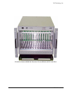
CT-400 Introduction 15
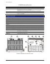
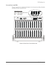
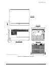
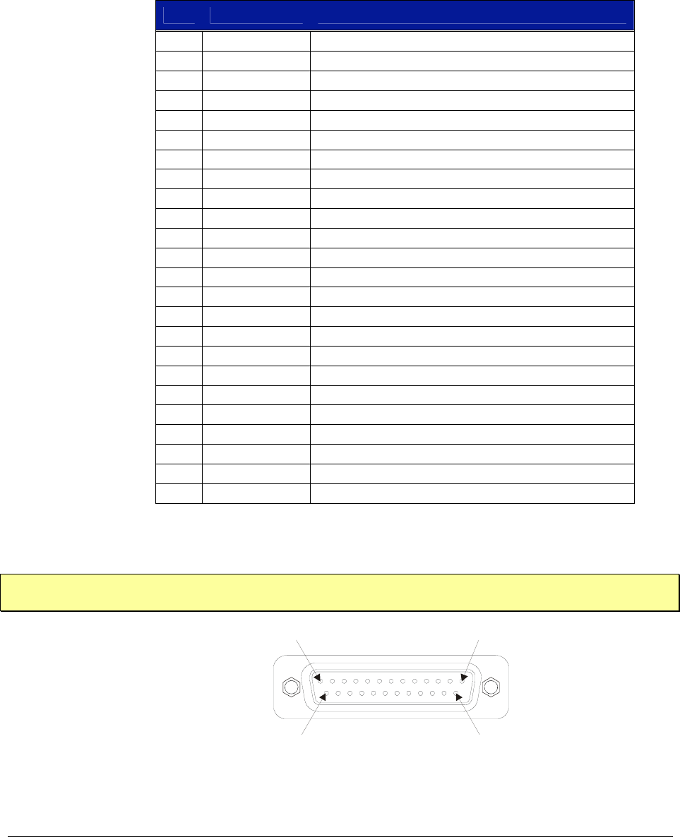
REAR PANEL MONITOR / CONTROL CONNECTOR
The 25-pin Monitor/Control Connector (see Figure 1-2) provides access to the backplane voltages
and other signals. The following table shows a pinout/signal list along with a brief description of
each. Refer to the pin locations in
Figure 1-4.
T
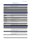
ABLE 1-1: MONITOR / CONTROL CONNECTOR PINOUT ASSIGNMENTS
PIN SIGNAL DESCRIPTION
1 -24 VMON VXIbus Voltage Monitor Output
2 GND Logic Ground
3 -2 VMON VXIbus Voltage Monitor Output
4 GND Logic Ground
5 +24 IMON Power Supply Current Monitor Output
6 -12 IMON Power Supply Current Monitor Output
7 -2 IMON Power Supply Current Monitor Output
8 -5.2 VMON VXIbus Voltage Monitor Output
9 RSV Reserved
10 +5 STANDBY VXIbus +5 V Standby Input
11 +5 VMON VXIbus Voltage Monitor Output
12 ACFAIL* VXIbus ACFAIL* Input or Monitor Output (see note)
13 RSV Reserved
14 GND Logic Ground
15 -12 VMON VXIbus Voltage Monitor Output
16 +24 VMON VXIbus Voltage Monitor Output
17 +12 VMON VXIbus Voltage Monitor Output
18 +12 IMON Power Supply Current Monitor Output
19 -24 IMON Power Supply Current Monitor Output
20 -5.2 IMON Power Supply Current Monitor Output
21 +5 IMON Power Supply Current Monitor Output
22 +5 STANDBY VXIbus +5 V Standby Input
23 R INHIBIT* Power Supply Remote Inhibit Input
24 GND Logic Ground
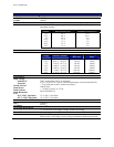
T
ABLE 1-2: MONITOR / CONTROL CONNECTOR PINOUT ASSIGNMENTS
NOTE Refer to VXIbus and VMEbus specifications for details on using the ACFAIL* and SYSRESET*
signals
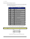
Pin 13
Pin 1
Pin 25
Pin 14
F
IGURE 1-4: DETAIL - MONITOR / CONTROL CONNECTOR PIN LOCATIONS