


VXI Technology, Inc.
48 CT-400 Operation
CT-400 MONITOR BOARD
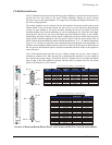
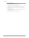
The CT-400 Monitor board provides monitoring of the mainframe’s operation and environment. It
provides the user with access to the seven VXIbus backplane voltages (to power external
circuitry), access to the eight backplane TTL trigger lines (for input and output) and control over
the unit’s cooling operation.
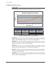
The cooling operation can be selected with the three-position fan speed switch located on the
Monitor board. In the low-speed position, the fans are run at a low speed providing adequate
cooling for most medium to low power modules. Running the fans at low speed will assure
minimum audible noise from the mainframe as well as increasing the life of the fan. In the high-
speed position, the fans are run at their maximum speed for maximum cooling. In the variable-
speed setting, the factory default, the fan speed is adjusted by the power drawn from the power
supply and the ambient temperature. The fan speed is equal to the low-speed setting when no
power is drawn from the backplane and the ambient temperature is 25 °C. As ambient temperature
rises to 45 °C, the fans are increased to the maximum speed in proportion to the temperature. In
addition, as the backplane loading increases from 0 W to 1000 W, the fan speed is increased from
the low speed to the maximum speed. It should be noted that both these factors work together to
set the fan speed.
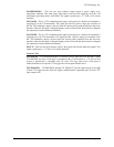
The CT-400 Monitor board provides all seven VXIbus voltages for user use. Each voltage is
available on connector J211 and is protected by a self-healing fuse rated for 1.0 A per voltage. In
the event that the current rating is exceeded or the line is shorted, the fuse will open and remain
open so long as the fault condition is present. Once the fault is removed, the fuse will restore
power to the connector in a few seconds.
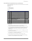
Pin 1
Pin 1
Pin 19
Pin 9
Pin 27
J211
J210
C
ONNECTOR
J211 S
IGNAL
A
SSIGNMENTS
C
ONNECTOR
J210 S
IGNAL
A
SSIGNMENTS
Pin 18
Pin 27
Pin 10
Pin 19
Pin 20
C
ONNECTOR
P
IN
F
UNCTION
C
ONNECTOR
P
IN
F
UNCTION
1 +5 Volts Output 20 Ground
2 -5.2 Volts Output 21 Ground
3 -2 Volts Output 22 Ground
4 +12 Volts Output 23 Ground
5 -12 Volts Output 24 Ground
6 +24 Volts Output 25 Ground
7 -24 Volts Output 26 Ground
8 Reserved 27 Ground
9 AMBTEMPOUT 28 Ground
10 Reserved 29 Ground
11 PWSOTEMP* 30 Ground
12 PWSOPWR* 31 Ground
13 PWSOVOLT* 32 Ground
14 PWSOCUR* 33 Ground
15 AMBOTEMP* 34 Ground
16 FANSPEEDLOW* 35 Ground
17 FANTECH1 36 Ground
18 FANTECH2 37 Ground
19 FAULT*
C
ONNECTOR
P
IN
F
UNCTION
C
ONNECTOR
P
IN
F
UNCTION
C
ONNECTOR
P
IN
F
UNCTION
1
TTLTRIGIN0
10
Ground
19 TTLTRIGOUT0
2
TTLTRIGIN1
11
Ground
20 TTLTRIGOUT1
3
TTLTRIGIN2
12
Ground
21 TTLTRIGOUT2
4
TTLTRIGIN3
13
Ground
22 TTLTRIGOUT3
5
TTLTRIGIN4
14
Ground
23 TTLTRIGOUT4
6 TTLTRIGIN5 15 Ground 24 TTLTRIGOUT5
7 TTLTRIGIN6 16 Ground 25 TTLTRIGOUT6
8 TTLTRIGIN7 17 Ground 26 TTLTRIGOUT7
9 Ground 18 Ground
PWS
PWS
PWS
PWS
FAN
FAN SPEED
HIGH
VAR
LOW
AMB
TEMP
PWR
VOLT
CUR
SPEED
TEMP
F
IGURE 3-2: MONITOR BOARD FRONT PANEL AND CONNECTOR PIN LOCATIONS & ASSIGNMENTS