


www.vxitech.com
CT-400 Operation 47
SECTION 3
OPERATION
INTRODUCTION
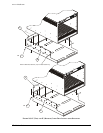
There are no operating instructions required for the CT-400 VXIbus mainframe. After the
mainframe is installed, operation is completely transparent to the operator. Just plug in the
instruments then power up the mainframe. The power supply lines and mainframe operation are
monitored and displayed to provide user-feedback of correct operation. Additionally, the user can
configure the CT-400 for remote power on operation if desired.
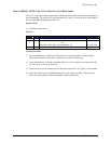
REMOTE POWER CONTROL
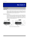
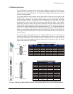
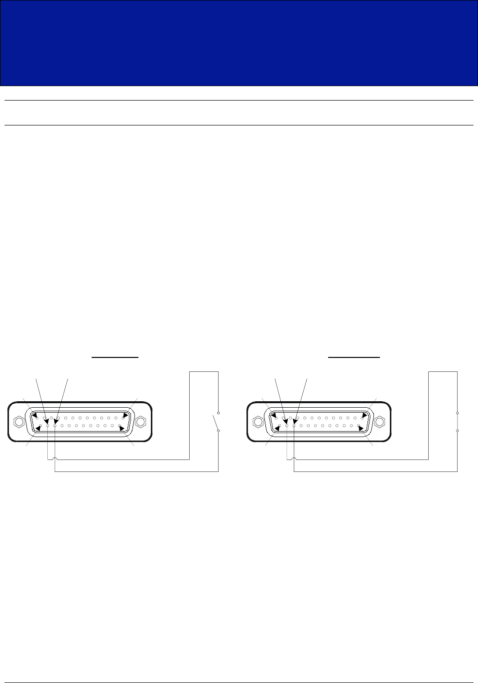
If the CT-400 mainframe is to be installed in a remote location, it is possible to apply and remove
power from the unit via the remote power pins located on connector J201. To utilize the remote
power feature, pins 23 and pin 24 should be connected as shown in
Figure 3-1. Internally, pin 23
is tied to a +5 V pull-up resistors. When a +5 V level is applied to pin 23, the CT-400 is in its
default state, with the power button indicating the power state of the chassis. When the switch is
closed and pins 23 and 24 are shorted, a 0 V level is applied to pin 23. With the +5 V level
removed, the chassis is then placed in the OFF state.
Pin 24 Pin 23
Pin 13
Pin 25 Pin 14
Pin 1
Pin 24
Pin 23
Power ON
Pin 24 Pin 23
Pin 13
Pin 25 Pin 14
Pin 1
Pin 24
Pin 23
Power OFF
F
IGURE 3-1: REMOTE POWER-ON SWITCH WIRING