


VXI Technology, Inc.
40 CT-400 Installation
OPTION 104 - HINGED CUSTOM FRONT PANEL INSTALLATION PROCEDURE
This kit includes the hardware found in Option 100 as well as the hardware necessary to install the
hinged custom front panel.
Required Tools
1) #2 Phillips Screw Driver
2) T15 Torx screwdriver
3) 3/8" Open Ended Wrench
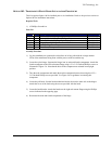
Parts List
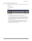
Item# Qty Description VTI P/N
1 2 Hinge, Adjustable Damping, Black 37-0066-000
2 4 Screw, 8-32 x 3/8" Flat Head Phillips, Zinc 37-0080-037
3 12 Screw, 8-32 x 5/8" Button Head Torx, Black Steel 37-0130-062
4 2 Handle, Chassis, 1 9/32" x 4", Black Aluminum 37-0134-000
5 1 Hinge, Support, Custom Door, Right Side, Nickel 37-0136-000
6 1 Hinge, Support, Custom Door, Left Side, Nickel 37-0136-001
7 1 Rack Mount Bracket, Standard, Left Side 41-0221-000
8 1 Rack Mount Bracket, Standard, Right Side 41-0221-001
9 1 Front Door, Application Specific 41-0229-000
10 1 Lower Support Bracket, App Spec Door 41-0230-000
11 1 Upper Support Bracket, App Spec Door 41-0231-000
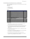
12 4 Washer, Split Lock, 8-32 Zinc 37-0013-008
13 4 Nut, Hex, 8-32, Zinc/Steel 37-0030-832
14 2 Screw, 8-32 x 3/8" Pan Head Phillips, Steel/Zinc 37-0074-037
15 2 Washer, Shoulder, 8-32, Nylon 37-0145-008
16 2 Standoff, 3/8" Hex, M/FM x 0.25, 10-32 M, 8-32 FM, SS 37-0146-000
17 12 Screw, 8-32 x 1/4", Truss Head Phillips, Blk Oxide 37-0038-025
18 8 Screw, 8-32 x 3/8" Pan Head Phillips, M/S, Blk Oxide 37-0079-037
Assembly Procedure
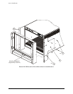
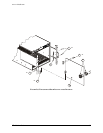
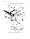
1) Lay the mainframe on a protected work surface on its long side with the voltage monitor
LEDs of the mainframe facing front with the power switch toward the top.
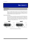
2) Locate the right and left side rack mount brackets. Install the rack mount brackets using eight
8-32 x 5/8" button head Torx screws. Refer to
Figure 2-7 for guidance. In order for the
custom panel to utilize the support hinges, the mainframe must be recessed by at least 6.5
inches (16.51 cm).
3) Locate the handles for the rack mount brackets. Use the 8-32 x 3/8" Phillips screws to install
these handles as shown in
Figure 2-7.
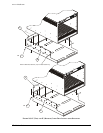
4) Locate the upper and lower support brackets. Attach these brackets to the rack mount flanges
above using the 8-32 x 1/4" black truss head Phillips screws.
5) Attach the standoffs to the rack mount brackets as indicated in
Figure 2-7 below.
6) Locate support brackets. Attach the support brackets to the appropriate rack mount flange
using an 8-32 x 3/8" pan head Phillips screw and a nylon washer.