


www.vxitech.com
CT-400 Installation 25
SECTION 2
INSTALLATION
INTRODUCTION
This section includes instructions on CT-400 configuration and installation. When the CT-400 is
unpacked from its shipping carton, the contents should include the following items:
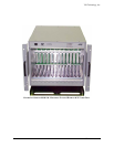
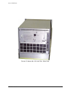
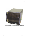
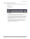
(1) CT-400 Thirteen-Slot Mainframe
(1) CT-400 User’s Manual (this manual)
(1) Power cord
All components should be immediately inspected for damage upon receipt of the unit.
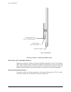
The power cord is the only way to disconnect the CT-400 mainframe from ac power.
Therefore, the power cord must be accessible to the operator at all times. When the CT-400
mainframe is mounted in a system rack, the power cord need not be accessible since the rack
must have its own disconnect device.
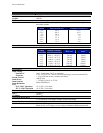
POWER REQUIREMENTS
The CT-400 is equipped with auto-ranging power supplies, which automatically sense the line
power value and set themselves accordingly. No voltage switch selection is required. When the
CT-400 is shipped, it is configured for a nominal line voltage of 115 V ac, with a 250 V, 15 A
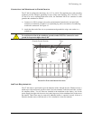
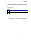
fuse installed. Fuse ratings are as follows:
90 V - 250 V Operation 15 A, 250 V, Slow Blow
207 V - 250 V Operation 10 A, 250 V, Slow Blow
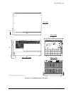
Do not attempt to change the fuse with the line cord connected. Ensure power is off and the
unit is unplugged before changing the fuse.
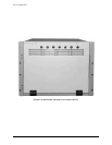
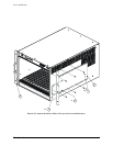
Refer to Figure 2-1 for the location of the fuse on the back panel.