


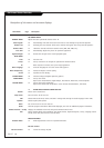

Viewing Equipment Setup
PAGE 14
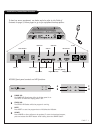
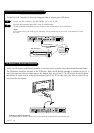
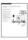
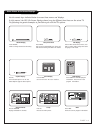
Connect the TV/STB to the display device that will be used to view the signal.
An unswitched AC power outlet is specifically provided on the TV/STB to plug the
display panel into.
RJP
INTERFACE
REMOTE
IN
AUDIO IN AUDIO OUT RS-232C
DISPLAY
CONTROL
AUX
CONTROL
DIGITAL
VIDEO OUT
AC IN
DIGITAL AUDIO
OUT (OPTICAL)
AC OUT
DIGITAL
VIDEO IN
MAX 8A 960W AC 120V~ 60Hz
12
. . . . . . . .
. . . . . . . .
. . . . . . . .
HCS5610 PTC INSTALLER MENU
UPN 000-000-000-000 FPGA E0F1
PTC V1.00.000 CPU V1.00.00
000 INSTALLER SEQ 000
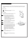
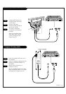
Plasma or LCD Display Panel Setup for use
with the TV/STB Commercial Interface
Control Box
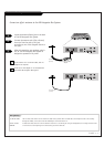
Connect RS-232C cable. (See previous page.)
Connect IR Receiver cable to Remote In
port.
Connect the Cable Out jack to the display
panel, typically the Antenna (In) jack.
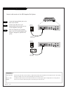
Plug the display panel AC power cord into
the convenience AC power outlet provided
on the TV/STB.
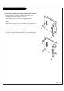
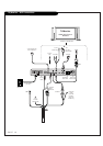
Plug the TV/STB AC power cord into a stan-
dard 120V 60 Hz power outlet.
Once power is applied to the TV/STB, the AC
power outlet is active. The LED on the dis-
play panel will turn red, indicating that the
panel is in standby mode.
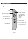
Use the user-supplied remote control to turn
on the TV/STB.
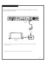
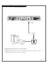
Connect Aux Control IR Output
as required of your system.
3.5mm Stereo Plug
with IR Receive
Antenna
Wall Jack
FR Coaxial Wire
(75ohm)
DVI
AC Power
Coad
3.5mm
Stereo Plug
Audio
R - L