Ventilation
PAGE 8
The HCS5610 Integrator Box as well as Plasma monitors generate heat during operation and need
to be provided with adequate ventilation to assure continued reliable operation. See recommenda-
tions below.
Proper clearance for air to flow around the HCS5610
Integrator Box must be provided.
Be sure proper ventilation is provided for the monitor, see monitor
installation guide for specified ventilation requirements.
Ventilation Clearance
Monitor Ventilation
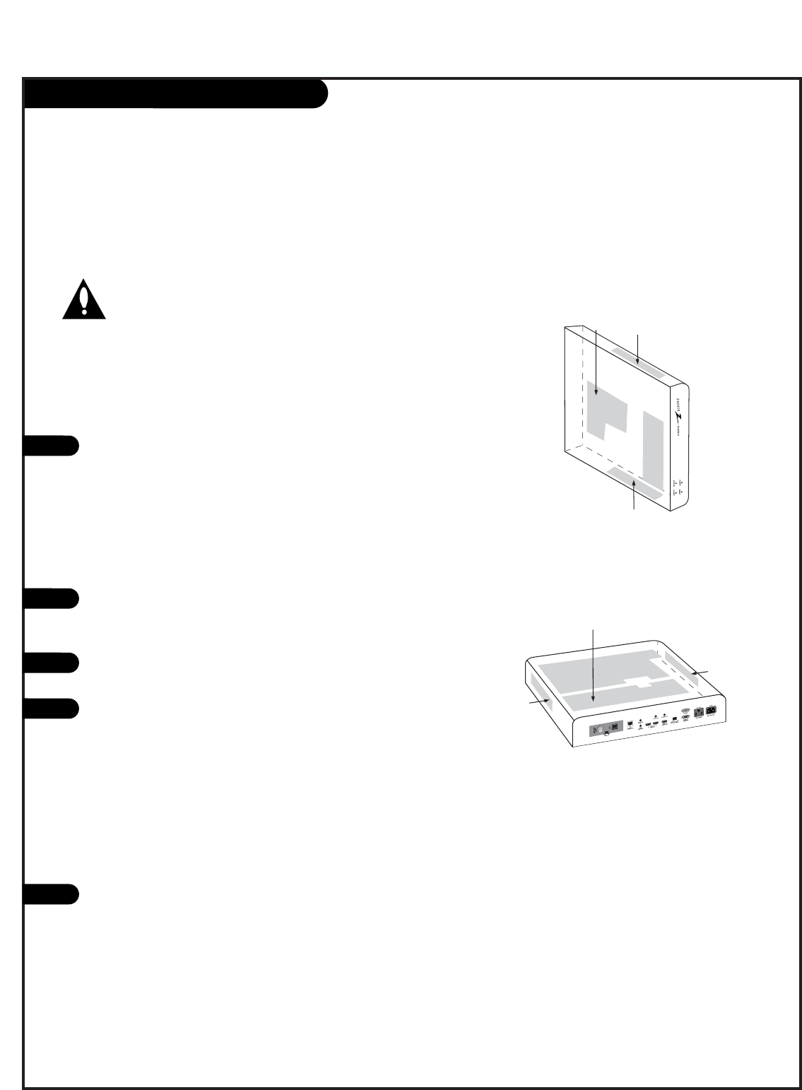
There are ventilation holes on four sides of the the
HCS5610 box provided for ventilation cooling.
a. If the box is mounted vertically, the vents on the
sides should be located on the top and bottom for
free vertical air movement.
b. If the box is mounted horizontally, the vents should
be located at the sides and top of the enclosure
(never mount the box with vents facing down). See
drawings to the right for reference.
The vent holes should never be blocked or obstructed to
airflow but have an unimpeded path through any enclo-
sure back to room temperature air.
The unit and its venting, should not be installed near
heat sources such as radiators or heating ducts.
If the unit is placed in an enclosure, tests should be run
to confirm that the ambient temperature around the unit
under normal expected operating conditions is stable and
does not exceed 40 degrees Celsius (104F). This can be
determined by placing a thermometer near the air intake
vents in the proposed enclosure and measuring the
temperature every hour, under normal operating
conditions, until two successive readings repeat.
If temperature does not stabilize but keeps increasing
above 104F, ventilation is inadequate and needs to be
improved.
Always provide adequate air space between the ventila-
tion areas and adjacent structures.
*Note:
In addition to the ventilation requirements shown, be sure to
allow enough clearance (4” - 5”) for wiring clusters attached to
the Integrator Box.
1
2
3
4
5
Vent Holes
Vent Holes
Vent Holes
Vent Holes
Vent Holes
Vent Holes


