PAGE 64
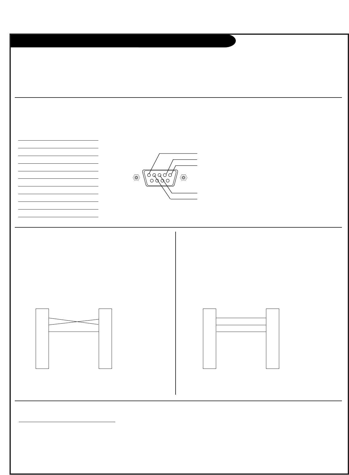
TV/STB RS-232 Monitor Requirements / RS-232 Troubleshooting
Type of Connector; D-Sub 9-Pin Female
Monitors listed below require RS-232 Null Modem DB9 Cable
with male connectors at each end. Depending on the type of
Null modem cable, one or two gender changers may be required.
3-Wire Configuration
(Serial male-male NULL modem cable)
RS-232C Null Configuration
Monitors listed below require RS-232 straight-through (extension)
DB9 cable with male connector on one end and female
connector on the other end.
Refer to monitor installation guide for more specifics.
RS-232 Pin Configuration Wiring Diagram
of the TV/STB Display Control Connector
RS-232 Communication Requirments
No. Pin Name
1 No Connection
2TXD (Transmit data)
3 RXD (Receive data)
4 No Connection
5 GND
6 No Connection
7 No Connection
8 No Connection
9 No Connection
5
2
1
3
4
1
2
3
4
5
6
7
8
9
NC
TXD
RXD
NC
GND
NC
NC
NC
NC
TV/STB
D-Sub 9-pin
Male
D-Sub 9-pin
Male
Monitors:
M3200C
M3700C
M4200C
M4600C
M3201C
M3701C
M4201C
M4210C
1
2
3
4
5
6
7
8
9
NC
TXD
RXD
NC
GND
NC
NC
NC
NC
Monitor
Null-Modem
Cable
3-Wire Configuration
(Straight-through male-female cable)
RS-232C Straight Configuration
1
2
3
4
5
6
7
8
9
NC
TXD
RXD
NC
GND
NC
NC
NC
NC
TV/STB
D-Sub 9-pin
Male
D-Sub 9-pin
Female
Monitors:
20LS7DC
26LC7DC
23LS7DC
32LC7DC
37LC7D
42LC7D
47LC7DF
32LC2DC
37LC2DC
50PC5DC
50PM1M
MU-60PZ95V
71PY1M
1
2
3
4
5
6
7
8
9
NC
RXD
TXD
GND
NC
NC
NC
NC
NC
Monitor
Straight-Through
or Extension
Cable
Impr
oper RS-232 Communications Setup
- Selects Incorrect Source at Power Up
TV/STB powers On TV. Flashes selected HDMI/DVI source but
selects incorrect Aux source.
-Check settings for Installer menu items 108, 109, 110 and 113.
- Displays ‘No Signal’ message at Power Off
TV/STB does not power Off TV and displays ‘No Signal’ message.
-Check settings for Installer menu items 108, 109, 110 and 113.
RS-232 Troubleshooting


