AVT 200HD Tuner • Installation 4
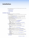
Installation
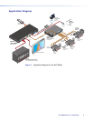
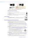
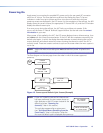
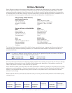
This section describes the rear panel of the AVT 200HD and provides instructions for cabling.
It covers the following topics:
• Installation Overview
• Rear Panel Features
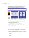
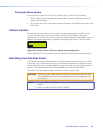
• Control Connections
Installation Overview
Follow these steps to install and set up the AVT 200HD tuner:
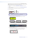
1. Disconnect power from the tuner and turn off all other devices that are connected to
it.
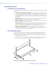
2. (Optional) Mount the unit in a rack. Rack mount the tuner using the supplied
brackets (see the “Mounting the Tuner” in the “Reference Information” section).
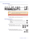
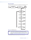
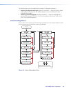
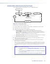
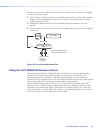
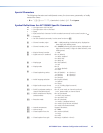
3. Connect the RF input. Connect an antenna or a CATV cable to the RF In F-type
connector (
j
on the rear panel diagram on the next page).
4. Connect the video output. Connect a television or other output device to one of
the following video output connectors:
• VID — Composite video (
b
, top, on the rear panel diagram)
• YC — S-video (
b
, bottom, on the rear panel diagram)
• RGBHV — RGBHV (
c on the rear panel diagram
)
• Component video — YUVp/HD or YUVi (
d
on the rear panel diagram
)
• HDMI — HDMI digital (
e
on the
rear panel diagram
)
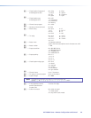
5. Connect the audio output. Connect a speaker set, amplifier, receiver, or other
audio output device to one or more of the following connectors:
• RCA — Unbalanced analog (
f
on the rear panel diagram)
• Captive screw — Balanced or unbalanced analog (
g
on the rear panel
diagram)
• Coax — Digital S/PDIF (
h
on the rear panel diagram)
• Optical — (Fiber optic) Digital S/PDIF (
i
on the rear panel diagram)
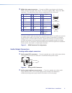
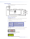
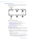
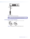
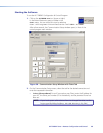
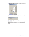
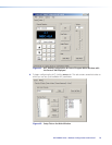
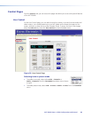
6. Connect control devices: Connect your computer to one of these AVT ports to
configure and control the tuner via the Windows
®
-based software or SIS commands.
• RS232 port — Serial RS-232 control (
k
on the rear panel diagram)
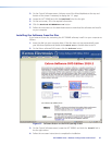
• LAN Ethernet port — Ethernet control via Internet browser (
l
on the rear panel
diagram)
• Config port — USB connection (
b
on the front panel diagram in the
“Operation” section)
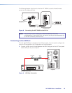
7. Connect power to the AVT by connecting a standard IEC power cord (provided) from
a 100 to 240 VAC, 50-60 Hz power source to the AC power receptacle (
a
on the rear
panel diagram).