


32 en | Hardware setup Divar XF
F.01U.135.429 | 2.5 | 2009.08 Installation manual Bosch Security Systems
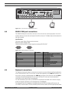
To communicate with the controllable camera, select a port number that is the same as the
input number to which the camera is connected (e.g. configure a controllable camera to port
16 if it is connected to channel 16).
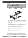
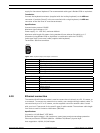
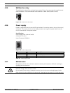
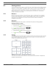
4.13 USB connectors
Four USB connectors are located at the rear panel of the unit. For convenience, one USB port
is located on the front of the unit to connect a mouse or memory device.
Figure 4.17 USB ports
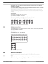
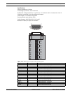
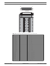
4.14 External alarm I/O connection
Alarm inputs and outputs are supplied via a 25-pole D-type socket. The screw terminal input/
output connection board supplied with the unit simplifies all alarm connections to the unit.
Connecting the inputs
Each (alarm) input line can be switched by a contact from devices such as pressure pads,
passive infra-red detectors, smoke detectors, and similar devices. Wire them as either N/O or
N/C. You can configure the alarm inputs as N/O or N/C in the menu system. The default is N/
O. Note that inputs 9-16 will not be used on an 8-channel Divar XF.
Specifications
Alarm input impedence: Internal pull-up 10 K to +5 V
Input voltage range: -5 VDC minimum to 40 VDC maximum
Input voltage treshold: low voltage 0.8 V maximum, high voltage 2.4 V minimum
Cable diameter: AWG 26-16 (0.13-1.5 mm2)
Connecting the alarm outputs
The four alarm output relays respond to input alarms and triggers. You can configure the
alarm outputs as N/O or N/C in the menu system. The relays are active for the duration of the
driving event. Connect the application to the alarm output relays (resistive loads only). Do not
exceed 30 Vac, 40 Vdc, 500 mA (continuous), or 10 VA on an alarm output relay's contacts.
Table 4.7 External alarm I/O
Specifications
Switching current (resistive): 500 mA maximum
Carrying power: 10 VA maximum
Switching voltage (resistive): 30 VAC / 40 VDC maximum
Cable diameter: AWG 26-16 (0.13-1.5 mm2)
USBUSB
Output number Function
1Alarm
2 Video loss
3 Controllable with control center
4 Controllable with control center
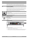
DANGER!
Electrical voltage.
Risk of electric shock and damage to the unit.
The contacts must not be used at AC line voltages.