


Manual Supplement
00809-0500-4530, Rev AA
October 2010
1-25
Rosemount 5300/5400 Series
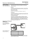
COMMON MODBUS
HOST CONFIGURATION
When using Modbus RTU or Modbus ASCII, the registers to receive status
and variables must be configured in the host system.
The transmission of single-precision (4 bytes) IEEE 754 floating point
numbers can be rearranged in different byte orders specified by the Floating
Point Format Code. The format code information, stated for each Remote
Terminal Unit (RTU) respectively, specifies which registers to poll from the
5300/5400 transmitter in order for the RTU to correctly interpret floating point
numbers. The byte transmission order for each format code is demonstrated
in Table 1-12 below.
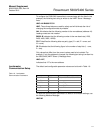
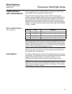
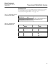
Table 1-12. Byte Transmission
Order is specified by the Floating
Point Format Code
NOTE
Some Modbus hosts cannot read the information described here using Input
Registers (Modbus function code 4). The Input Register information can also
be read using Holding Register (Function code 3). In this case, Input Register
number + 5000 is used as Holding Register number.
Between host system and device, it is recommended to use 60 seconds or
less between polls, and three retries.
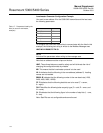
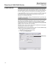
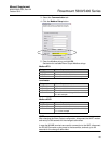
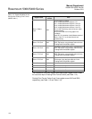
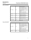
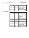
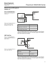
Input Registers The register area starting with 1300 can be configured to have any of the four
format codes. The configuration is done by setting FloatingPointFormatCode
register (holding register 3000) to 0-3, as shown in Table 1-12. This
configuration can be done with the Rosemount Radar Master program.
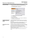
NOTE
Depending on the slave number the 5300/5400 transmitter is using, different
registers must be used with the default slave number being 1. Slave number
is determined by the HART address.
Format
Code
Byte transmission
order
Description
0 [AB] [CD] Straight word order, most significant byte first
1 [CD] [AB] Inverse word order, most significant byte first
2 [DC] [BA] Inverse word order, least significant byte first
3 [BA] [DC] Straight word order, least significant byte first