


Manual Supplement
00809-0500-4530, Rev AA
October 2010
Rosemount 5300/5400 Series
1-32
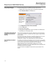
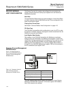
Thermo Electron Autopilot
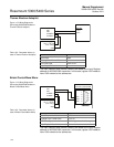
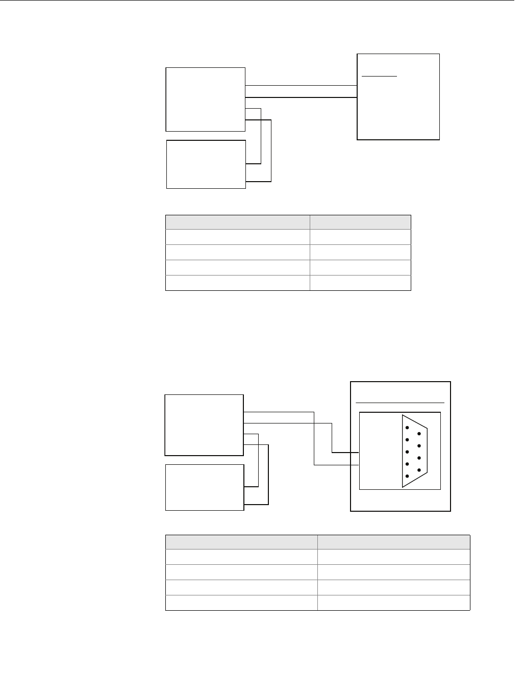
Figure 1-12. Wiring Diagram for
Connecting 5300/5400 Modbus to
Thermo Electron Autopilot
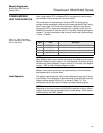
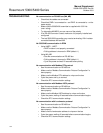
Table 1-22. Parameter Values (in
case of Thermo Electron Autopilot)
The Input Register Base Number needs to be added to the Input Register
address of the 5300/5400 transmitter. In this case, register 1302 needs to
have 1302 entered as the address etc.
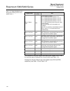
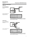
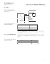
Bristol ControlWave Micro
Figure 1-13. Wiring Diagram for
Connecting 5300/5400 Modbus to
Bristol ControlWave Micro
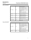
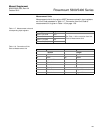
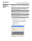
Table 1-23. Parameter Values (in
case of Bristol ControlWave Micro)
The Input Register Base Number needs to be added to the Input Register
address of the 5300/5400 transmitter. In this case, register 1302 needs to
have 1303 entered as the address etc.
CEB TB1
1 RX +
2 RX -
MA
MB
POWER +
POWER -
AutoPILOT
5300/5400 Modbus
Power Supply
+ 8 to + 30 Vdc
(max. rating)
GND
Parameter Value
Baud Rate 9600
Floating Point Format Code 1
RTU Data Type IEEE Flt 2R
Input Register Base Number 0
Com Port 3 (C3) RS-485
1
2
3
4
5
TXD-
TXD+
GND
6
7
8
9
MA
MB
POWER +
POWER -
ControlWave Micro
5300/5400 Modbus
Power Supply
+ 8 to + 30 Vdc
(max. rating)
GND
DB9 Male
Parameter Value
Baud Rate 9600
Floating Point Format Code 2 (FC 4)
RTU Data Type 32-bit registers as 2 16-bit registers
Input Register Base Number 1