


Manual Supplement
00809-0500-4530, Rev AA
October 2010
Rosemount 5300/5400 Series
1-4
MECHANICAL
INSTALLATION
For instructions on how to mount the Rosemount 5300/5400 transmitter, refer
to the Rosemount 5300 Series Reference Manual (Document No.
00809-0100-4530), and the Rosemount 5400 Series Reference Manual
(Document No. 00809-0100-4026).
ELECTRICAL
INSTALLATION
NOTE
For general electrical installation requirements, including grounding
requirements, refer to Rosemount 5300 Series Reference Manual (Document
No. 00809-0100-4530), and the Rosemount 5400 Series Reference Manual
(Document No. 00809-0100-4026).
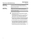
To connect the Rosemount 5300/5400:
1. Disconnect/shut off the electrical power to transmitter head and then
open the instrument cover. Do not remove the cover in an explosive
atmosphere with a live circuit.
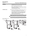
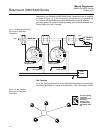
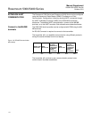
2. Pull the cable through the cable gland/conduit. For the RS-485 bus, use
shielded twisted pair wiring, preferably with an impedance of 120
(typically 24 AWG) in order to comply with the EIA-485 standard and
EMC regulations. The maximum cable length is 4000 ft/1200 m.
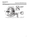
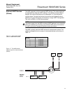
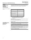
3. Make sure that the transmitter housing is grounded, then connect wires
according to Figure 1-2 and Table 1-1. Connect the lead that originates
from the “A” line from the RS-485 bus to the terminal marked MB, and
the lead that originates from the “B” line to the terminal marked MA.
4. If it is the last transmitter on the bus, connect the 120
termination resistor.
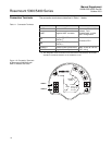
5. Connect the leads from the positive side of the power supply to the
terminal marked POWER +, and the leads from the negative side of the
power supply to the terminal marked POWER -. The power supply
cables must be suitable for the supply voltage and ambient temperature,
and approved for use in hazardous areas, where applicable.
6. Attach and tighten the housing cover. Tighten the cable gland, then plug
and seal any unused terminals, and connect the power supply.