


Manual Supplement
00809-0500-4530, Rev AA
October 2010
Rosemount 5300/5400 Series
1-26
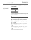
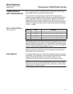
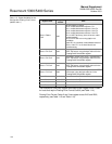
Table 1-13. Output Variables for the
Configurable Floating Point Format
(default code 1)
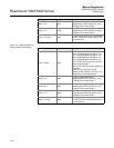
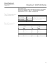
The Rosemount 5300/5400 register area starting with register 2000 is used
for hosts that require Floating Point Format Code 0 (see Table 1-14).
Floating Point Format Codes 2 and 3 use register areas 2100 and 2200,
respectively (see Table 1-15 and Table 1-16).
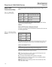
Register Name
Register
Number
Note
Slave 1 Status
Conf
1300
Bit information in bitfield.
Bit 0: Invalid Measurement Slave 1 PV.
Bit 1: Invalid Measurement Slave 1 Non PV.
Bit 2: Invalid Measurement Slave 1 Non PV.
Bit 3: Invalid Measurement Slave 1 Non PV.
Bit 14: HART bus busy (slave in burst or other
master present)
Bit 15: HTM Task not running (option not
available).
Note: Bit 1-3 is set when Invalid Measurement of
Slave 1 Non PV. i.e. all three bits are set
simultaneously.
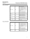
Slave 1 PV Conf 1302
Primary variable from slave 1 represented in
IEEE 754 format, using the byte order set in the
FloatingPointFormatCode register.
Slave 1 SV Conf 1304
Secondary variable from slave 1 represented in
IEEE 754 format, using the byte order set in the
FloatingPointFormatCode register.
Slave 1 TV Conf 1306
Tertiary variable from slave 1 represented in
IEEE 754 format, using the byte order set in the
FloatingPointFormatCode register.
Slave 1 FV Conf 1308
Fourth variable from slave 1 represented in IEEE
754 format, using the byte order set in the
FloatingPointFormatCode register.
Slave 2 data 1310-1318 Same data as for Slave 1.
Slave 3 data 1320-1328 Same data as for Slave 1.
Slave 4 data 1330-1338 Same data as for Slave 1.
Slave 5 data 1340-1348 Same data as for Slave 1.