


Manual Supplement
00809-0500-4530, Rev AA
October 2010
Rosemount 5300/5400 Series
1-8
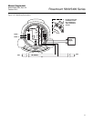
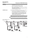
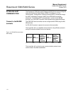
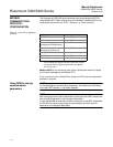
Alternatively, the Rosemount 5300/5400 Series Transmitters can be installed
as shown in Figure 1-5. If this wiring layout is used, there is an increased risk
for communication disturbances due to differences in potential between
grounding points. By using the same grounding point for Modbus Master and
Power Supply, this risk is reduced.
Figure 1-5. Alternative Multidrop
Connection of 5300/5400
Transmitters
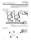
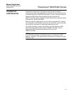
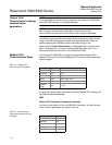
Star Topology
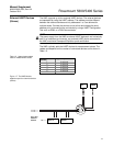
For a Star Topology Connection of the 5300/5400 transmitters, the transmitter
with the longest cable run needs to be fitted with a 120- termination resistor.
Figure 1-6. Star Topology
Connection of 5300/5400
Transmitters
MODBUS
POWER
HART
(RS-485)
HART to Modbus Converter
MB
MA
-
-
+
+
MODBUS
POWER
HART
(RS-485)
HART to Modbus Converter
MB
MA
-
-
+
+
Ambients > 60 ºC
Use wiring rated
for min 90 ºC
Ambients > 60 ºC
Use wiring rated
for min 90 ºC
Power
Supply
120
120
RS-485 Bus
B
A
Modbus
Master
Z
External
Ground Screw
External
Ground Screw
Internal
Ground Screw
Internal
Ground Screw
MODBUS
POWER
HART
(RS-485)
HART to Modbus Converter
MB
MA
-
-
+
+
MODBUS
POWER
HART
(RS-485)
HART to Modbus Converter
MB
MA
-
-
+
+
MODBUS
POWER
HART
(RS-485)
HART to Modbus Converter
MB
MA
-
-
+
+
MODBUS
POWER
HART
(RS-485)
HART to Modbus Converter
MB
MA
-
-
+
+
MODBUS
POWER
HART
(RS-485)
HART to Modbus Converter
MB
MA
-
-
+
+
MODBUS
(RS-485)
v
erter
MB
MA
-
Ambients > 60 ºC
Use wiring rated
for min 90 ºC
Ambients > 60 ºC
Use wiring rated
for min 90 ºC
Ambients > 60 ºC
Use wiring rated
for min 90 ºC
Ambients > 60 ºC
Use wiring rated
for min 90 ºC
Ambients > 60 ºC
Use wiring rated
for min 90 ºC
For Star Topology
connection,
connect the 120
termination
resistor to the
transmitter with
the longest cable
run.