


Manual Supplement
00809-0500-4530, Rev AA
October 2010
1-7
Rosemount 5300/5400 Series
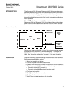
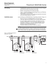
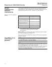
RS-485 Bus • The 5300/5400 transmitters do not provide electrical isolation between
the RS-485 bus and the transmitter power supply
• Maintain a bus topology and minimize stub length
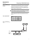
• Figure 1-4 identifies multidrop wiring topology, where up to 32 devices
may be wired on one RS-485 bus
• The RS-485 bus needs to be terminated once at each end, but should
not be terminated elsewhere on the bus
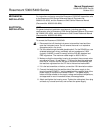
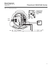
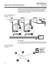
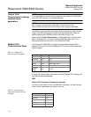
Installation cases Install the Rosemount 5300/5400 Series Transmitters as shown in Figure 1-4.
• Use common ground for Modbus Master and Power Supply
• The Power cables and RS-485 Bus are in the same cable installation
• An ground cable is installed and shall be used (cable size ≥4 mm
according to IEC60079-14, or size according to applicable national
regulations and standards). A properly installed threaded conduit
connection may provide sufficient ground.
• The cable shielding is grounded at master site (optional)
NOTE
The HMC equipped transmitter contains intrinsically safe circuits that require
the housing to be grounded in accordance with national and local electrical
codes. Failure to do so may impair the protection provided by the equipment.
Figure 1-4. Multidrop Connection of
5300/5400 Transmitters
MODBUS
POWER
HART
(RS-485)
HART to Modbus Converter
MB
MA
-
-
+
+
MODBUS
POWER
HART
(RS-485)
HART to Modbus Converter
MB
MA
-
-
+
+
Ambients > 60 ºC
Use wiring rated
for min 90 ºC
Ambients > 60 ºC
Use wiring rated
for min 90 ºC
Power
Supply
120
120
RS-485 Bus
B
A
Modbus
Master
Z
External
Ground Screw
Internal
Ground Screw
External
Ground Screw
Internal
Ground Screw