


MODEL TCL SECTION 1
DESCRIPTION AND SPECIFICATIONS
1.3 SPECIFICATIONS — MODEL 54e-24 ANALYZER
1.2 SPECIFICATIONS — SAMPLE CONDITIONING SYSTEM
3
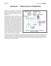
GENERAL
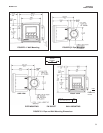
Enclosure: Fiberglass reinforced polyester, NEMA 3
(IP53) suitable for marine environments
Dimensions: 14.5 x 13.0 x 8.6 in. (369 x 329 x 218 mm)
Mounting: Wall
Ambient Temperature: 32° - 122°F (0 - 50°C)
Ambient Humidity: 0 - 90% (non-condensing)
Power: 115 Vac, 6.9 W, 50/60 Hz;
230 Vac, 7.0 W, 50/60 Hz
Hazardous Location: The TCL sample conditioning sys-
tem has no hazardous location approvals.
Pumps:
EN 809:1998
Weight/Shipping Weight: 14 lb/16 lb (6.5 kg/7.5 kg)
SAMPLE REQUIREMENTS
Inlet Connection: compression fitting, accepts 1/4 in. OD
tubing
Drain Connection: 3/4 in. barbed fitting (must drain to
open atmosphere)
Inlet Pressure: <100 psig (791 kPa abs)
Flow: at least 0.25 gph (15 mL/min)
Temperature: 32 - 122°F (0 - 50°C)
Total Alkalinity: <300 mg/L as CaCO
3
. For samples con-
taining <50 mg/L alkalinity, consult the factory.
SAMPLE CONDITIONING SYSTEM
Reagent: Potassium iodide in vinegar.
Reagent Usage: 5 gallons lasts approximately 60 days.
Reagent Pump: Fixed speed peristaltic pump, about
0.2 mL/min
Sample Pump: Fixed speed peristaltic pump, about 11 mL/min
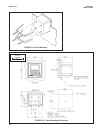
Case: Epoxy-painted cast aluminum, NEMA4X (IP65).
Dimensions: 5.7 x 5.7 x 5.2 in. (144 x 144 x 132 mm),
DIN size panel cut-out.
Front Panel: Membrane keypad with tactile feedback.
Three green LEDs indicate alarm status. Red LED
indicates fault condition.
Conduit Openings: Accepts PG 13.5 or 1/2 inch conduit
fittings
Display: Three-line, back-lit, dot matrix LCD, 70 x 35 mm.
First line is measurement reading. Second line is tem-
perature and current output. Third line is user-selec-
table. Character heights: 1st line - 16 mm (0.6 in.),
2nd and 3rd lines - 7 mm (0.3 in.).
Ambient Temperature and Humidity: 0 to 50°C (32 to
122°F). 95% (maximum) non-condensing.
Analyzer can be operated between -20 and 60°C
(-4 to 140°F) with some degradation in display quality.
Power: 100-127 Vac ± 10%, 50/60 Hz ± 6%, 8 W
200-253 Vac ± 10%, 50/60 Hz ± 6%, 8 W
Hazardous Location: Applies to analyzer only, not to system
Class I, Division 2, Groups A, B, C, & D.
T5 Ta=50°C. Dust ignition proof: Class II,
Division 1, Groups E, F, & G; Class III.
FM: Max. relay contact rating: 28 Vdc
resistive
150 mA - Groups A & B;
400 mA - Group C;
540 mA - Group D
CSA:
Max. relay contact rating:
28 Vdc; 110 Vac; 230 Vac;
6 amps resistive. Enclosure Type 4.
RFI/EMI: EN-61326
LVD: EN-61010-1
Outputs: Two 4-20 mA or 0-20 mA isolated outputs.
Continuously adjustable. Outputs can be assigned to
chlorine or temperature. Output dampening is user-
selectable. Maximum load at 115/230 Vac is 600Ω.
Maximum load at 100/200 Vac is 550Ω. Output 1 has
superimposed HART signal (options -261 and -263).
Outputs can be programmed for PID control (options
-262 and -263).
Alarms:
Relay 1 - Process, Interval, or Time Proportional
Control (TPC requires code -262 or -263)
Relay 2 - Process, Interval, or Time Proportional
Control (TPC requires code -262 or -263)
Relay 3 - Process, Interval, or Time Proportional
Control (TPC requires code -262 or -263)
Relay 4 - Sensor/analyzer and process fault alarm
Each relay has a dedicated LED on the front panel.
Relay Contacts: Relays 1-3: Epoxy sealed form A
contacts, SPST, normally open
Relay 4: Epoxy sealed form C, SPDT
Resistive
Inductive
28 Vdc 5.0 Amps 3.0 Amps
115 Vac 5.0 Amps 3.0 Amps
230 Vac 5.0 Amps 1.5 Amps
Weight/Shipping Weight: 5 lb/6 lb (2 kg/2.5 kg)