


64
MODEL TCL SECTION 12
MAINTENANCE
FIGURE 12-13.
FIGURE 12-14.
FIGURE 12-16.
FIGURE 12-15.
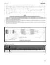
check
valve
air outlet
air inlet
12.3.4 Replacing the air pump
1. Disconnect power to the analyzer.
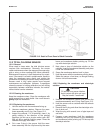
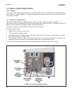
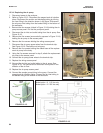
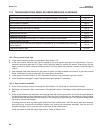
2. Refer to Figure 12-13. Disconnect the reagent and air injection
tubes. Disconnect the suction and discharge tubing by turning
the Luer fitting in the direction shown in the figure. Disconnect
the air pump inlet tubing from the barbed fitting in the bottom of
the enclosure.
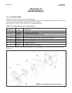
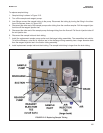
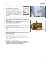
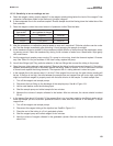
3. Remove the four screws (circled in Figure 12-14) holding the air
pump access panel. Pull out the pump and panel.
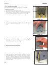
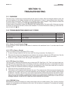
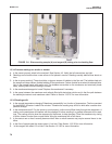
4. Disconnect the air inlet and outlet tubing from the air pump. See
Figure 12-15.
5. Remove the five screws (surrounded by squares in Figure 12-14)
holding the air pump to the access panel.
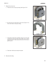
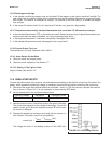
6. Remove the four screws holding the wiring access panel.
7. Disconnect the air pump power wires from the terminal strip.
See Figure 12-16. Discard the old air pump.
8. Remove the five screws holding the rubber base of the replace-
ment air pump to the body.
9. Using the five screws removed in step 6, attach the replacement
air pump to the access panel.
10. Connect the air pump power wires to the terminal strip.
11. Replace the wiring access panel.
12. Connect the air inlet and outlet tubing to the air pump. See
Figure 12-15. The conical end of the check valve points in the
direction of the air flow.
13. Replace the air pump access panel.
14. Connect the sample pump tubing to the pump. Connect the
reagent and air injection tubing. Connect the air inlet tubing to
the barbed fitting at the bottom of the enclosure.
Model option -11 115 Vac only
Model option -12 230 Vac only