


MODEL TCL TABLE OF CONTENTS
TABLE OF CONTENTS CONT'D.
LIST OF FIGURES
Number Title Page
1-1 Dimensions of TCL Case ........................................................................................ 6
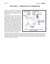
2-1 Schematic of Sample Conditioning System and Analyzer .................................... 7
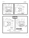
3-1 Panel Mount Installation ......................................................................................... 9
3-2 Pipe Mount Installation............................................................................................ 10
3-3 Surface Mount Installation ...................................................................................... 11
3-4 Installing the Sample Conditioning Enclosure......................................................... 12
3-5 [something] ............................................................................................................. 13
4-1 Removing the Knockouts ....................................................................................... 14
4-2 Wiring Connections for Model 54e-01-10 (Panel Mount with 115/230 Vac Power).. 15
4-3
Wiring Connections for Model 54e-01-11 (Pipe/Surface Mount with 115/230 Vac Power) ... 15
4-4 Chlorine sensor with Standard Cable...................................................................... 16
4-5 Chlorine sensor with Optimum EMI/RFI or Variopol Cable..................................... 16
6-1 Displays During Normal Operation ........................................................................ 18
6-2 Solu Comp II Keypad.............................................................................................. 18
7-1 High Alarm Logic .................................................................................................... 24
7-2 Low Alarm Logic...................................................................................................... 24
8-1 Determination of Total Chlorine .............................................................................. 34
8-2 Sensor Current as a Function of Total Chlorine Concentration............................... 34
8-3 Dual Slope Calibration ............................................................................................ 37
9-1 Exploded View of 54e Analyzer (Panel Mount Version) ......................................... 39
9-2 Exploded View of 54e Analyzer (Wall Mount Version) ........................................... 40
9-3 Sensor Parts ........................................................................................................... 42
9-4 Replacing Reagent Tubing...................................................................................... 43
9-5 Replacing Sample Tubing....................................................................................... 44
9-6 Replacing Peristaltic Pump Tubing — step 2.......................................................... 45
9-7 Replacing Peristaltic Pump Tubing — step 3.......................................................... 45
9-8 Replacing Peristaltic Pump Tubing — step 4.......................................................... 45
9-9 Replacing Peristaltic Pump Tubing — step 6.......................................................... 45
9-10 Replacing Peristaltic Pump Tubing — step 7a........................................................ 46
9-11 Replacing Peristaltic Pump Tubing — step 7b........................................................ 46
9-12 Replacing Peristaltic Pump Tubing — step 7c........................................................ 46
10-1 Disconnecting Sample and Reagent Tubing Prior to Checking Flow ..................... 51
10-2 Simulating Chlorine................................................................................................. 52
iii