


MODEL TCL SECTION 4
WIRING
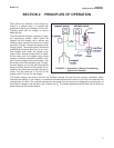
4.3 MAKE POWER, ALARM, OUTPUT AND SENSOR CONNECTIONS IN THE ANALYZER
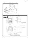
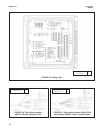
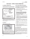
Refer to Figure 4-2. Make power and alarm connections on TB3. Make analog output wiring connections on TB2. For
access to power and alarm terminals, loosen the screw holding the protective cover in place and remove the cover.
DANGER
Live voltages may be present.
Will cause severe injury or death.
Alarm contacts are dry (i.e., not powered) and are normally open. Refer to Section 1.0 for relay specifications.
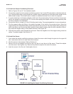
For best EMI/RFI protection, shield the output cable and enclose it in an earth-grounded, rigid, metal conduit.
Connect the outer shield of the output cable to the earth ground connection on TB2 (see Figure 4-2).
Keep sensor and output signal wiring separate from power wiring. Do no run sensor and power cables in the same
conduit or close together in a cable tray.
AC wiring must be 14 gauge or greater. Be sure to connect earth ground from the power cable to the nearby
ground lug. A good earth ground is necessary for proper operation of the controller. Provide a switch or breaker to
disconnect the analyzer from the main power supply. Install the switch or breaker near the analyzer and label it as
the disconnecting device.
WARNING: RISK OF ELECTRICAL SHOCK
AC connections and grounding must comply with UL 508 or local electrical code. DO NOT apply
power to the analyzer until all electrical connections are verified and secure.
NOTE
The Model 54eA analyzer leaves the factory configured for use with the Model 499ADO oxygen
sensor. Because a 499ADO sensor is NOT used in the TCL system, turn to Section 7.5 and con-
figure the analyzer to read total chlorine before wiring the sensor to the analyzer. Operating the
analyzer and sensor for longer than five minutes while the analyzer is improperly configured will
greatly increase the stabilization time for the sensor.
Be sure to turn off power to the analyzer before wiring the sensor.
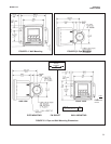
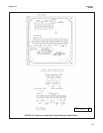
The wiring label, which is shown in Figure 4-3, is a general purpose label. It has wiring information concerning
other sensors, for example, contacting and inductive conductivity sensors, that can be used with the 54e instru-
ment platform. For total chlorine measurements, only TB3 is used.
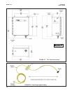
Refer to Figures 4-4 and 4-5 for sensor wiring. Use the pigtail wire and wire nuts provided with the sensor when
more than one wire must be attached to a single terminal
14