


46
MODEL TCL SECTION 9
CALIBRATION - TOTAL CHLORINE
SECTION 9
CALIBRATION - TOTAL CHLORINE
9.1 INTRODUCTION
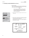
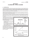
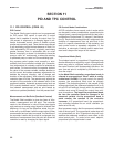
The continuous determination of total chlorine requires two steps. See Figure 9-1. First, the sample flows into a
conditioning system (Model TCL) where it is treated with acetic acid (vinegar) and potassium iodide. The acid low-
ers the pH, which allows total chlorine in the sample to quantitatively oxidize the iodide to iodine. The treated sam-
ple then flows to the sensor. The sensor is a membrane-covered amperometric sensor, whose output is propor-
tional to the concentration of iodine. Because the concentration of iodine is proportional to the concentration of
total chlorine, the analyzer can be calibrated to read total chlorine.
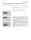
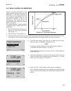
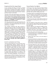
Figure 9-2 shows a typical calibration curve for a total chlorine sensor. Because the sensor really measures iodine,
calibrating the sensor requires exposing it to a solution containing no iodine (zero standard) and to a solution con-
taining a known amount of iodine (full-scale standard).
The zero standard is necessary because the sensor, even when no iodine is present, generates a small current
called the residual current. The analyzer compensates for the residual current by subtracting it from the measured
current before converting the result to a total chlorine value. New sensors require zeroing before being placed in
service, and sensors should be zeroed whenever the electrolyte solution is replaced. Deionized water is a good
zero standard.
The purpose of the full-scale standard is to establish the slope of the calibration curve. Because stable total chlo-
rine standards do not exist, the sensor must be
calibrated against a test run on a grab sample
of the process liquid. Several manufacturers
offer portable test kits for this purpose.
Observe the following precautions when taking
and testing the grab sample.
• Take the grab sample from a point as close
as possible to the inlet of the TCL sample
conditioning system.
• Total chlorine solutions are unstable. Run
the test immediately after taking the sam-
ple. Try to calibrate the sensor when the
chlorine concentration is at the upper end
of the normal operating range.
The Model 499ACL-02 (total chlorine) sensor
loses sensitivity at high concentrations of chlo-
rine. The 54eA controller has a dual slope fea-
ture that allows the user to compensate for the
non-linearity of the sensor. However, for the
vast majority of applications, dual slope cali-
bration is unnecessary.
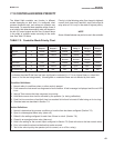
FIGURE 9-1. Determination of Total Chlorine
FIGURE 9-2. Sensor Current as a Function of Total
Chlorine Concentration