


MODEL TCL SECTION 12
MAINTENANCE
59
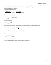
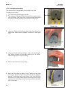
6. Hold the sensor at about a 45-degree angle with the cathode end pointing up. Add electrolyte solution (see
Section 12.2.4) through the fill hole until the liquid overflows. Tap the sensor near the threads to release
trapped air bubbles. Add more electrolyte solution if necessary.
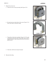
7. Place the fill plug in the electrolyte port and begin screwing it in. After several threads have engaged, rotate
the sensor so that the cathode is pointing up and continue tightening the fill plug. Do not overtighten.
8. Place a new O-ring in the groove around the cathode post. Cover the holes at the base of the cathode stem
with several drops of electrolyte solution.
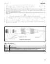
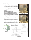
9. Insert a small blunt probe, like a toothpick with the end cut off, through the pressure equalizing port. See
Figure 12-3.
NOTE
Do not use a sharp probe. It will puncture the bladder and destroy the sensor.
Gently press the probe against the bladder several times to force liquid through the holes at the base of the
cathode stem. Keep pressing the bladder until no air bubbles can be seen leaving the holes. Be sure the holes
remain covered with electrolyte solution.
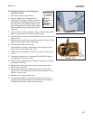
10. Place a drop of electrolyte solution on the cathode, then place the membrane assembly over the cathode.
Screw the membrane retainer in place.
11. The sensor may require several hours operating at the polarizing voltage to equilibrate after the electrolyte
solution has been replenished.
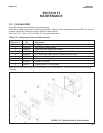
FIGURE 12-3. Sensor Parts
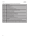
33523-00 Electrolyte Fill Plug
9550094 O-Ring, Viton 2-014
33521-00 Membrane Retainer
23501-02 Total Chlorine Membrane Assembly: includes one membrane assembly and one O-ring
23502-02 Total Chlorine Membrane Kit: includes 3 membrane assemblies and 3 O-rings
9210438 Total Chlorine Sensor Fill Solution, 4 oz (120 mL)
TABLE 12-3. Spare Parts