


MODEL TCL SECTION 13
TROUBLESHOOTING
SECTION 13.
TROUBLESHOOTING
13.1 OVERVIEW
The Solu Comp II continuously monitors itself and the sensor for faults. When the analyzer detects a fault, the
word fault appears in the display alternately with the measurement. If alarm 3 was configured as a fault alarm,
the alarm relay will energize. The outputs do not change during a fault condition. They continue to reflect the
measured chlorine or temperature. Press to display the fault codes.
A large number of information screens are available to aid troubleshooting. The most useful of these are raw sen-
sor current and sensitivity and zero current at last calibration. To view the information screens, go to the main dis-
play and press the key.
13.2 TROUBLESHOOTING USING FAULT CODES
13.2.1 Sensor Current Exceeds 210 μA
Excessive sensor current implies that the sensor is miswired or the membrane is torn. It can also mean the sen-
sor has failed.
13.2.2 RTD is Open or Shorted.
There is an open or short in the sensor RTD or wiring.
A. If sensor is being installed for the first time, check the wiring connections. See Section 4.3.
B. Disconnect the sensor from the analyzer and measure the resistance between the RTD lead wires. See the
sensor manual to identify the RTD leads. If there is an open or short circuit, replace the sensor.
C. If there is no open or short, check the analyzer. See Section 13.5
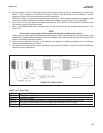
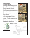
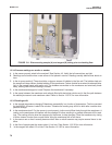
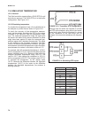
13.2.3 RTD Sense Line is Open.
The Solu Comp II measures temperature using a three-wire RTD. See Figure 13-3. The in and return leads con-
nect the RTD to the measuring circuit in the analyzer. A third wire, called the sense line, is connected to the return
line. The sense line allows the analyzer to correct for the resistance of the in and return leads and to correct for
changes in lead wire resistance caused by changes in ambient temperature.
A. Verify that all wiring connections are secure.
B. The analyzer can be operated with the sense line open. The measurement will be less accurate because the
analyzer can no longer correct for lead wire resistance and for changes in lead wire resistance with ambient
temperature. However, if the sensor is to be used at approximately constant temperature, the lead wire resist-
ance error can be eliminated by calibrating the sensor at the measurement temperature. Errors caused by
changes in lead wire resistance with changes in ambient temperature cannot be eliminated.To make the error
message disappear, connect the RTD sense and return terminals with a jumper.
13.2.4 EEPROM Failure.
EEPROM failure means the analyzer is unable to store data in the non-volatile memory. Thus, if power is lost then
restored, all configurations and calibrations will be lost. Call the factory for assistance. The analyzer will probably
need to be replaced.
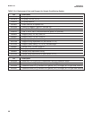
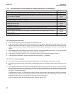
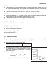
Fault Code Explanation See Section
S1 Out of Range Sensor current exceeds 210 μA (chlorine only) 13.2.1
TC1 Open RTD is open 13.2.2
TC1 Shorted RTD is shorted 13.2.2
S1 Sense Line Open RTD sense line is open 13.2.3
EEPROM Failure EEPROM failure 13.2.4
67