


11
MODEL TCL SECTION 3
INSTALLATION
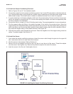
3.2.3 Install the Sample Conditioning Enclosure
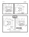
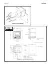
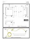
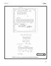
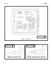
1. Refer to Figures 3-6 and 3-7 for installation details.
2. Connect the sample line to the sample conditioning system. Use ¼-inch OD hard plastic or stainless steel tub-
ing. If dechlorinated water is being measured, provide a way of substituting a chlorinated water sample for the
dechlorinated sample. Chlorinated water is needed to calibrate the sensor and to check its response.
3. If a grab sample tap is not already available, install one in the process piping. Choose a point as close as pos-
sible to the sample line supplying the TCL. Be sure that opening the sample valve does not appreciably alter
the flow of sample to the instrument.
4. Connect the drain to a length of ¾-inch ID flexible plastic tubing. The sample must drain to open atmosphere.
5. Find the reagent tubing and fitting in the plastic bag taped to the inside of the enclosure door. Screw the
reagent fitting onto the bulkhead fitting at the bottom left of the enclosure. Pass the reagent tubing through the
hole in the carboy cap. Be sure the plastic weight will be inside the carboy when the cap is placed on the car-
boy. Attach the reagent tubing to the barbed connector. See Figure 3-8.
6. Place the blue plastic carboy beneath the enclosure. Place the weighted end of the reagent tubing inside the
carboy. To prepare reagent, see Section 5.2.
3.2.4 Install the Sensor
1. From inside the sample conditioning enclosure, thread the sensor cable through the gland on the upper left
side. Leave about one foot of cable inside the enclosure.
2. Wire the sensor to the analyzer. Refer to Section 4.3.
3. Remove the nut and adapter from the flow cell. Slip the nut over the end of the sensor. Thread the adapter
onto the sensor. Hand tighten only. Remove the protective cap from the end of the sensor.
4. Insert the sensor in the flow cell. Hand tighten the nut.
FIGURE 3-6. Installing the Sample Conditioning Enclosure